Operation Manual
EN
USB AUDIO INTERFACE

Main Features
UR22C Operation Manual 2
Contents
Main Features ...........................................2
Panel Controls and Terminals ................3
Front Panel ..........................................................3
Rear Panel ...........................................................5
Software ....................................................6
Yamaha Steinberg USB Driver ............................6
dspMixFx UR-C....................................................8
Dedicated Windows for Cubase Series .............13
Sweet Spot Morphing Channel Strip ..................16
REV-X ................................................................18
Guitar Amp Classics ..........................................20
Using with a Computer ..........................23
Connection Example..........................................23
Configuring Audio Driver Settings on the DAW
Software.............................................................24
Recording/Playback ...........................................25
Using with an iOS Device ......................27
Connection Example..........................................27
Recording/Playback ...........................................28
Troubleshooting.....................................30
Appendix.................................................33
Limitations on the use of effects ........................33
Computer connector types .................................33
Signal Flows.......................................................34
Block Diagrams..................................................35
Technical Specifications ....................................37
General Specifications .......................................38
Uninstalling TOOLS for UR-C ............................39
Main Features
2 x 2 USB 3.0 Audio Interface with 2 x
D-PRE and 32-bit/192 kHz support
The UR22C is a 2-in and 2-out USB 3.0 audio
interface, featuring two world-renowned D-PRE
microphone preamps and supporting 192 kHz and
32-bit audio quality to capture all the subtleties and
expressiveness of any audio source.
True 32-bit resolution
The UR22C and the Yamaha Steinberg USB Driver
support the 32-bit Integer format, which can
represent audio data in higher resolution compared
to Float format. Together with a DAW (such as
Cubase) which can fully utilize the 32-bit Integer
data, they enable unprecedented audio resolution in
your music production.
USB 3.0 & USB Type-C
The UR22C is equipped with a USB Type-C port and
features USB 3.0 (USB 3.1 Gen 1) SuperSpeed
mode. It also provides full compatibility with the
USB 2.0 High-Speed mode and includes a Type-C
to Type-A cable.
dspMixFx
The dspMixFx technology is powered by the latest
SSP3 DSP chip and offers latency-free monitoring
with highly acclaimed DSP effects, including REV-X
reverb, for users of any DAW software.
Panel Controls and Terminals
UR22C Operation Manual 3
Panel Controls and Terminals
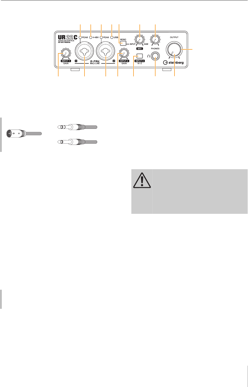
Front Panel
1 [MIC/LINE 1] jack
For connection to a microphone or digital instrument. This
jack can be connected to both XLR-type and phone-type
(balanced/unbalanced) plugs.
NOTE
The phantom power will be supplied to the XLR jack connected
to the [MIC/LINE 1] jack.
2 [INPUT 1 GAIN] knob
Adjusts the input signal level of the [MIC/LINE 1] jack.
3 [MIC/LINE 2] jack
For connection to a microphone, digital instrument,
electric guitar, or electric bass. This jack can be
connected to both XLR-type and phone-type (balanced/
unbalanced) plugs.
NOTE
The phantom power will be supplied to the XLR jack connected
to the [MIC/LINE 2] jack.
4 [INPUT 2 GAIN] knob
Adjusts the input signal level of the [MIC/LINE 2] jack.
5 [PEAK] indicator
Lights up according to the input signal. Lights up when
the input signal is 3 dB below the clipping level.
6 [+48V] indicator
Lights up when the [+48V] switch (phantom power) is
turned on.
7 [USB] indicator
Lights up when the power is turned on and the unit is
communicating with the computer or iOS device. The
indicator flashes continuously when the computer or iOS
device does not recognize the device.
8 [INPUT 2 HI-Z] switch
Switches the input impedance (on O/off N). Turn this
switch on when connecting high impedance instruments,
such as an electric guitar or electric bass, directly to the
[MIC/LINE 2] jack. When you turn this switch on, use an
unb
alanced phone plug for connection between the
instruments and the [MIC/LINE 2] jack.
NO
TICE
Do not connect or disconnect any cables while turning on the
[INPUT 2 HI-Z] switch. Doing so can damage the connected
device and/or the unit itself.
NOTE
• If you use a balanced phone plug, the device will not work
correctly.
• When the HI-Z switch is turned on, the signal from the XLR-
type is cut off.
9 [MONO] switch
When this switch is on, the input to the [MIC/LINE 1/2]
jacks is output to both the [MAIN OUT L/R] jacks and the
L/R channel of the [PHONES] jack. When the switch is off,
the input to the [MIC/LINE 1] jacks is output to the [MAIN
OUT L] jack and the input to the [MIC/LINE 2] jacks is
output to the [MAIN OUT R] jack.
For the [PHONES] jack, the input to the [MIC/LINE 1]
jacks is output to the L channel and the input to the [MIC/
LINE 2] jacks is output to the R channel.
Plug types
Setting optimum recording levels
Adjust the [INPUT GAIN] knobs so that the [PEAK]
indicator flashes briefly at the loudest input volume.
XLR-type (balanced)
Phone-type (balanced)
Phone-type (unbalanced)
CAUTION
To protect your speaker system, leave the
monitor speakers turned off when turning the
[INPUT 2 HI-Z] switch on/off. It’s also a good idea
to turn all output level controls down to their
minimum. Neglect of these precautions may
result in loud noise bursts that may damage
your equipment, your ears, or both.

Panel Controls and Terminals
UR22C Operation Manual 4
) [MIX] knob
Adjusts the signal level balance between the input signal
to the [MIC/LINE 1/2] jacks and the signal from an
application, such as DAW software. Operation of this
control knob does not affect the signal sent to a computer.
! [PHONES ] jack
For connection to a set of stereo headphones.
@ [PHONES] knob
Adjusts the output signal level of the [PHONES] jack.
# [OUTPUT] knob
Adjusts the output signal level of the [MAIN OUTPUT]
jacks.
$ POWER indicator
Lights up when the power is turned on. The indicator
flashes continuously if the power supply is insufficient. In
this case, use the USB power adapter or USB mobile
battery.
Using the Mix knob
Turn the [MIX] knob to the [DAW] side if the input
volume is high and to the [INPUT] side if the input
volume is low. When the knob is turned fully to the
[DAW] side, only the input sound from DAW can be
heard.
Panel Controls and Terminals
UR22C Operation Manual 5
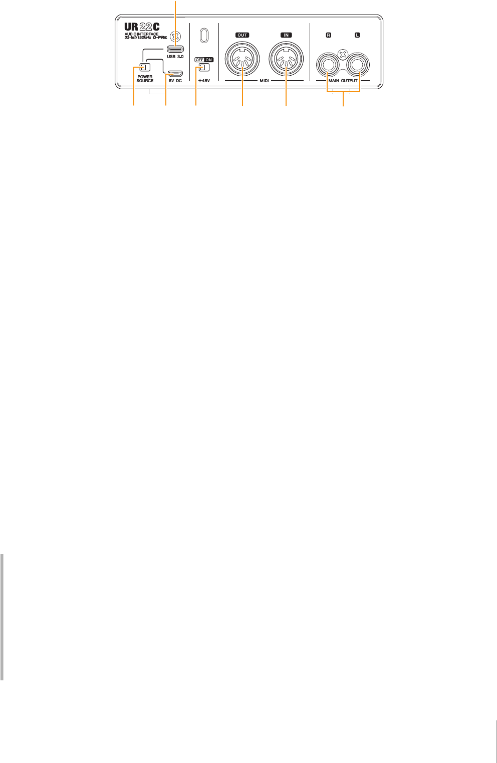
Rear Panel
1 [POWER SOURCE] switch
For selecting the port for supplying power to the UR22C.
To supply bus power via the [USB 3.0] port, set this switch
to the [USB 3.0] side. To supply power via the [5V DC]
port, set this switch to the [5V DC] side.
2 [USB 3.0] port
For connection to a computer or iOS device.
NOTICE
When connecting to a computer with a [USB 3.0] port,
observe the following to prevent the computer from freezing
or shutting down, as well as corruption or even loss of data.
• Before connecting/disconnecting the USB cable, be sure to
observe the following points.
- Quit all open software applications on the computer.
- Set all output level controls to the minimum.
• Wait at least six seconds between connecting/
disconnecting the USB cable.
NOTE
Apple accessories may be required when connecting the UR22C
with iOS devices. For details, refer to the UR22C Startup Guide.
3 [5V DC] port
For connecting a USB power adapter or USB mobile
battery. Use a power supply when connecting the UR22C
to a device that does not supply sufficient bus power,
such as an iPad. (The UR22C does not include a USB
power adapter or USB mobile battery.)
NOTICE
• Read the safety precautions for the USB power adapter or
USB mobile battery that you use.
• Use a USB power adapter or USB mobile battery that can
supply power in compliance with USB standards with a 5-
pin micro USB plug.
Output voltage 4.8 V to 5.2 V
Output current 0.9 A or greater
4 [+48V] switch
Turns the phantom power on/off. When you turn this switch
on, phantom power will be supplied to the XLR jack
connected to the [MIC/LINE 1/2] jacks. Turn this switch on
when using a phantom powered condenser microphone.
NOTICE
When using phantom power, observe the following to prevent
noise and possible damage to UR22C or connected
equipment.
• Do not connect or disconnect any devices while the
phantom power switch is turned to ON.
• Set all output level controls to the minimum before turning
the phantom power switch to ON or OFF.
• When connecting devices not requiring phantom power to
the [MIC/LINE 1/2] jack, make sure to turn the phantom
power switch to OFF.
NOTE
When the phantom power switch is turned on and off, all inputs/
outputs will be muted for a few seconds.
5 [MIDI OUT] jack
For connection to the MIDI IN jack of the MIDI device.
Transmits MIDI signals from the computer.
6 [MIDI IN] jack
For connection to the MIDI OUT jack of the MIDI device.
Receives and inputs MIDI signals to the computer.
NOTE
• Select [Steinberg UR22C-port1] for the MIDI port when using a
MIDI jack with an iOS app. Please note that [Steinberg UR22C-
port2] is not available.
• Do not activate dspMixFx when using a MIDI device. This may
interfere with stable data transmission/reception.
7 [MAIN OUTPUT L/R] jacks
For connection to monitor speakers. These jacks can be
connected to phone-type (balanced/unbalanced) plugs.
This outputs the MIX 1 signals. To adjust the output signal
level, use the [OUTPUT] knob on the front panel.
Using the [5V DC] port
Even when the UR22C is connected to a computer, you
can supply power via the [5V DC] port by external
power supply if the [POWER SOURCE] switch is set to
the [5V DC] side. This can be used to avoid power
supply problems. For example, ground loops due to
differences in voltage potential can occur if the device
connected to the UR22C is using the same power outlet
as the computer, and audio quality degradation can
occur if the power supply from the computer’s USB port
is not stable.
Software
UR22C Operation Manual 6
Software
The section explains software operations for using the
UR22C with a computer.
Yamaha Steinberg USB Driver
Yamaha Steinberg USB Driver is a software program that
allows communication between the UR22C and a
computer. In Control Panel, you can configure the basic
settings for the audio driver (Windows) or confirm the
audio driver information (Mac).
How to Open the Window
Windows
• From the start menu, select [Yamaha Steinberg USB
Driver] [Control Panel].
• From the Cubase series menu, select [Studio] [Studio
Setup] [Yamaha Steinberg USB ASIO] [Control
Panel].
Click the upper tabs to select the desired window.
Mac
• Select [Application] [Yamaha Steinberg USB Control
Panel]
• From the Cubase series menu, select [Studio] [Studio
Setup] [Steinberg UR22C (High Precision)]
[Control Panel] [Open Config App]
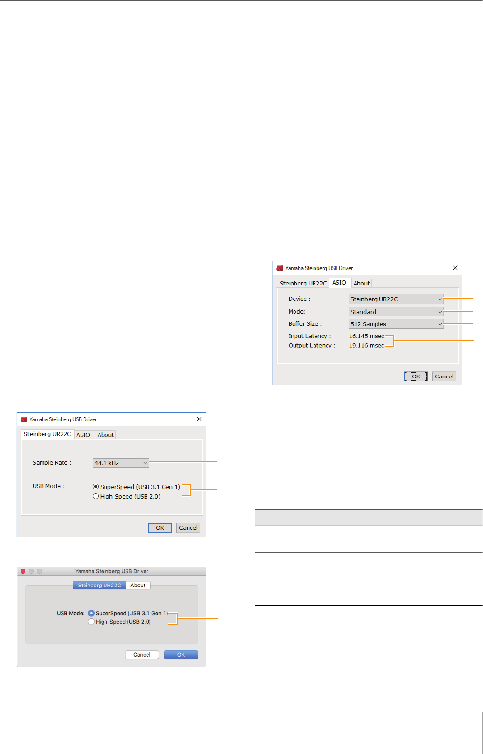
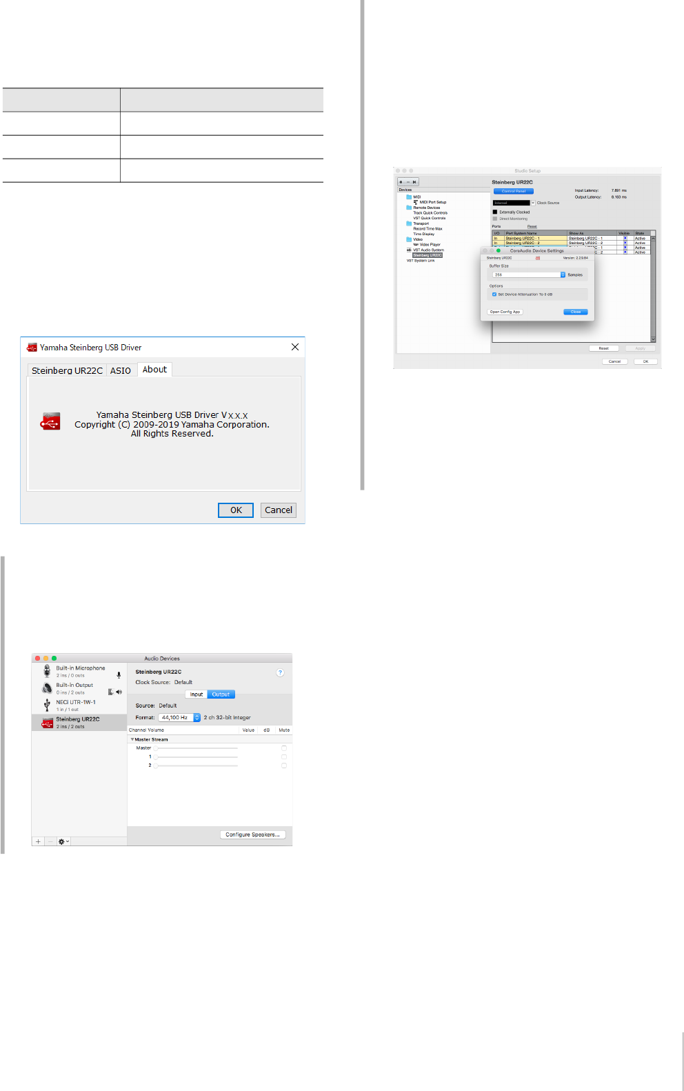
Steinberg UR22C Window
These windows are for selecting the sample rate and the
USB mode.
Windows
Mac
1 Sample Rate
Lets you select the sample rate of the device.
Settings: 44.1 kHz, 48 kHz, 88.2 kHz, 96 kHz, 176.4 kHz,
192 kHz
NOTE
The available sample rates may differ depending on the
particular DAW you’re using.
2 USB Mode
Lets you select the USB mode. The default setting is
SuperSpeed (USB 3.1 Gen 1) mode.
Settings: SuperSpeed (USB 3.1 Gen 1), High-Speed (USB 2.0)
NOTE
If High-Speed (USB 2.0) mode is used, the data bandwidth will
become narrower, but this will not affect the functionality of the
UR22C. Other performance values such as latency will not
change.
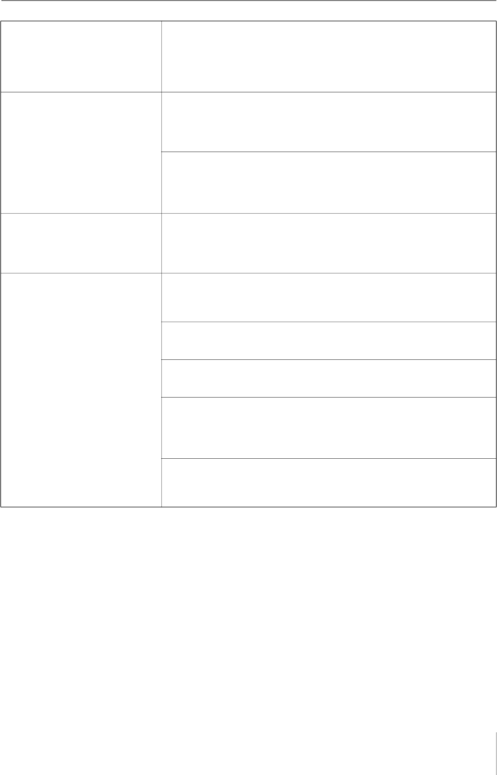
ASIO Window (Windows only)
For selecting the ASIO driver settings.
1 Device
Lets you select the device for use with the ASIO driver.
This function is available when connecting two or more
devices that are compatible with the Yamaha Steinberg
USB Driver to the computer.
2 Mode
Lets you select the latency mode.
Settings: Low Latency, Standard, Stable
Sample Rate Descriptions
Low Latency Low latency mode. High-performance
computer is required.
Standard Standard latency mode.
Stable High latency mode. This prioritizes
stability for low-performance computer
and high-load projects.
Software
UR22C Operation Manual 7
3 Buffer Size
Lets you select the buffer size for the ASIO driver. The
range varies depending on the specified sample rate. The
lower the value of the ASIO buffer size, the lower the value
of audio latency.
4 Input Latency/Output Latency
Indicates the latency (delay time) for the audio input and
output in millisecond units.
About Window
Indicates the version and copyright information of the
audio driver.
Sample Rate Range
44.1 kHz / 48 kHz 32 Samples – 2048 Samples
88.2 kHz / 96 kHz 64 Samples – 4096 Samples
176.4 kHz / 192 kHz 128 Samples – 8192 Samples
How to Select the Sample Rate (Mac)
You can select the sample rate in the [Audio MIDI
Setup] window. Select the sample rate from the
[Applications] [Utilities] [Audio MIDI Setup]
[Format] menu.
How to Select the Buffer Size (Mac)
You can select the buffer size in the settings window for
each application (DAW software, etc.).
From the Cubase series menu, select [Studio]
[Studio Setup], then click [Control Panel] in [Steinberg
UR22C] or [Steinberg UR22C (High Precision)] in the
menu on the left side of the window.
The method for opening the settings window is different
for each application.
Using with 32-bit Integer processing (Mac)
[Steinberg UR22C] or [Steinberg UR22C (High
Precision)] is shown in the [ASIO Driver] setting on the
Cubase series program. Select [Steinberg UR22C
(High Precision)] when processing at 32-bit integer
resolutions between Cubase and the driver.
Software
UR22C Operation Manual 8
dspMixFx UR-C
This software is for operating the convenient built-in DSP
mixer and DSP effects. The DSP mixer allows you to mix
up to two input channels down to one stereo output. A
number of DSP effects for processing the input signals are
also provided, and since the processing/mixing is
hardware-based, there is no monitoring latency.
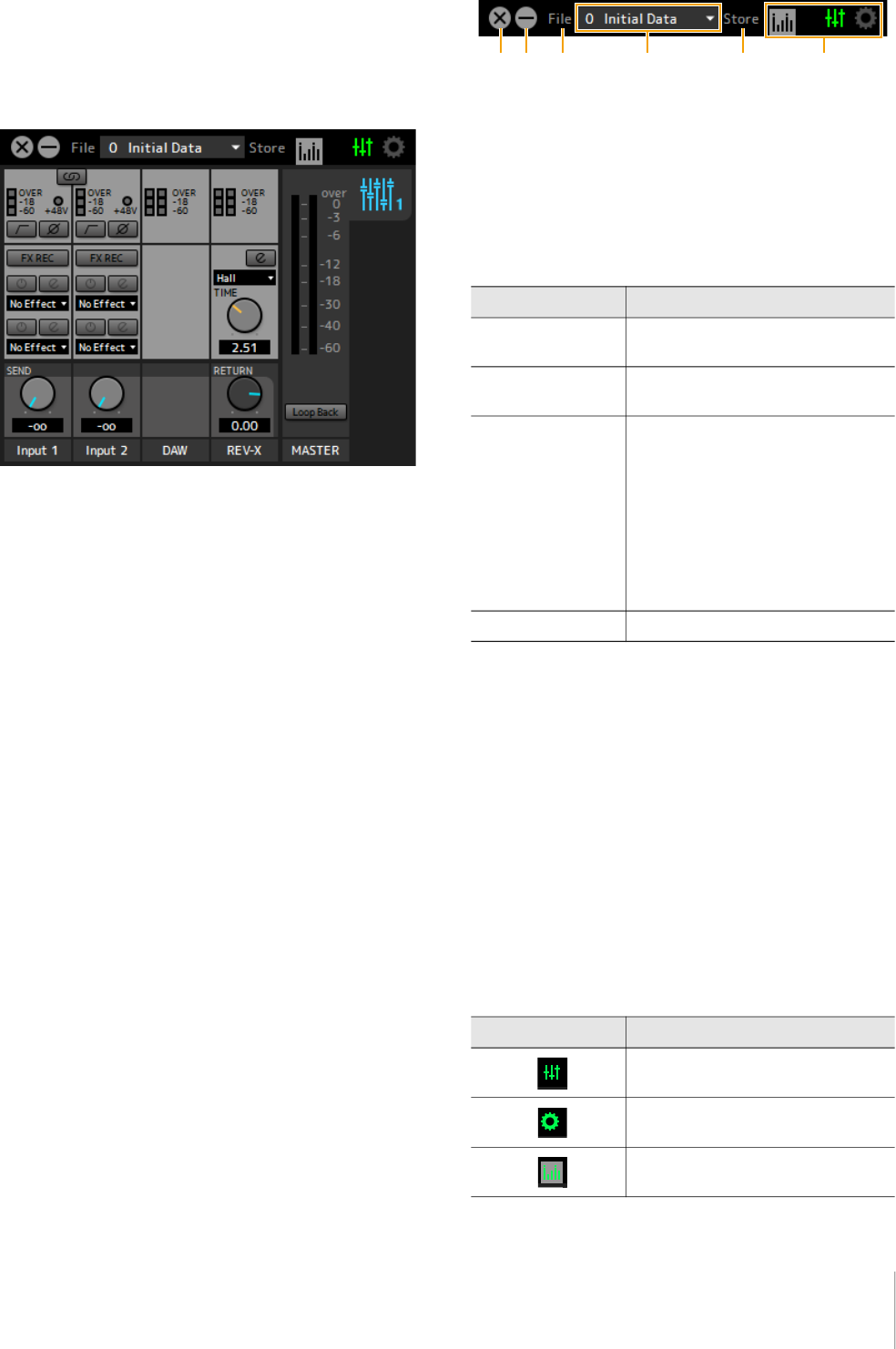
Screenshot
How to Open the Window
Windows
[All Programs] or [All apps] [Steinberg UR22C]
[dspMixFx UR-C]
Mac
[Application] [dspMixFx UR-C]
Tool Area
This is the area for configuring the overall common
settings of dspMixFx UR-C.
1 Quit
Quits dspMixFx UR-C.
2 Minimize
Minimizes the dspMixFx UR-C window.
3 File
Provides four different menus for various settings.
4 Scene
Indicates the scene name. You can change the scene
name by clicking on it. Clicking the button on the right
opens the window for calling up other scenes. Call up the
desired scene by clicking it. To cancel calling up the
scene, click outside of the window.
5 Store
Opens the Scene Store window. Enter the desired scene
name into the STORE NAME field. Select the destination
for storing the scene in the No. NAME field. Click [OK] to
store the scene.
6 Selecting windows
Selects the desired dspMixFx UR-C window. The selected
window icon lights in red.
Menu Descriptions
Open Opens the settings file of dspMixFx
UR-C.
Save Saves the settings file of dspMixFx UR-
C to a computer.
Import Scene Imports a scene from the settings file of
dspMixFx UR-C. Select the desired
settings file of dspMixFx UR-C and
import the desired scene on the left
side of the [IMPORT SCENE] window.
The window appears after the file is
selected in the file selection dialog.
Select the destination for importing on
the right side of the window. Click [OK]
to import it.
Initialize All Scenes Initialize all the saved scenes.
Menu Description
Main window
Setup window
Information window
Software
UR22C Operation Manual 9
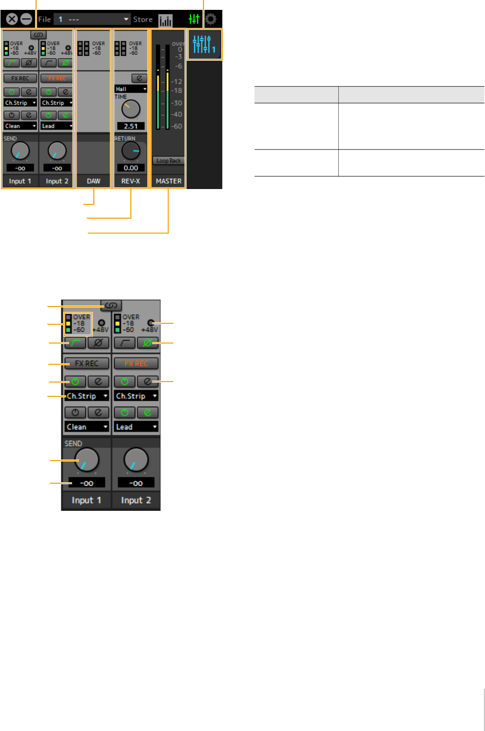
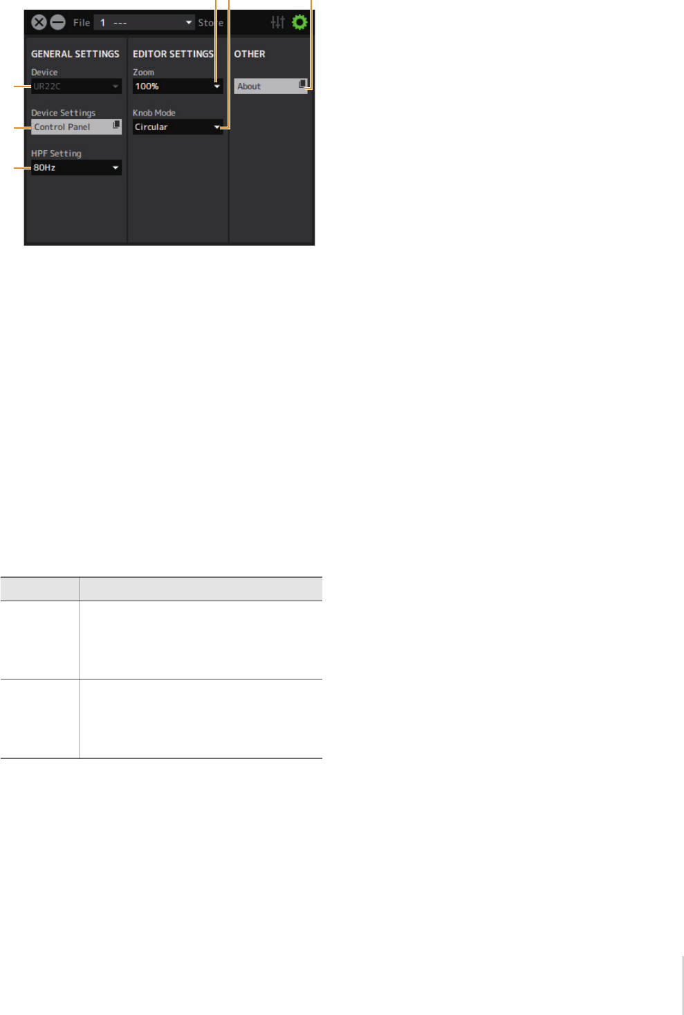
Main Window
This window is for configuring the entire signal flow.
Channel Area
This is the area for configuring the input channel settings.
1 Channel Link
Turns on (lit) and off (unlit) the channel link function of two
adjacent channels. When this is on, two mono channels
will become one stereo channel.
2 Level Meter
Indicates the signal level.
3 +48V
Indicates the on/off status of the phantom power function
of the device.
4 High Pass Filter
Turns on (lit) and off (unlit) the high pass filter. To select
the cutoff frequency of the high pass filter, use the “Setup
Window” (page 12) in the section “dspMixFx UR-C.”
5 Phase
Turns on (lit) and off (unlit) the phase inversion of the
signal.
6 FX REC
Turn the FX REC (effect recording) on and off.
7 Effect On/Off
Turns the Effect on (lit) and off (unlit).
8 Effect Edit
Opens (lit) and closes (unlit) the selected effect setup
window.
9 Effect Type
Selects the effect type.
Settings: NoEffect, Ch.Strip, Clean, Crunch, Lead, Drive
NOTE
The maximum number of Channel Strip and Guitar Amp Classics
iterations which can be used simultaneously is limited. Refer to
the “Limitations on the use of effects” (page 33).
) REV-X Send
Adjusts the signal level which is sent to REV-X.
Range: -∞ dB − +6.00 dB
! REV-X Send Value
Displays and adjusts the REV-X send value. Enable
editing of the value by double clicking the number.
Channel Area (page 9) MIX Area (page 11)
DAW Area (page 10)
Master Area (page 11)
REV-X Area (page 10)
Settings Description
On (lit) Applies an effect to both the monitor
signal (sent to the device) and the
recording signal (sent to the DAW
software).
Off (unlit) Applies an effect to only the monitor
signal (sent to the device).
Software
UR22C Operation Manual 10
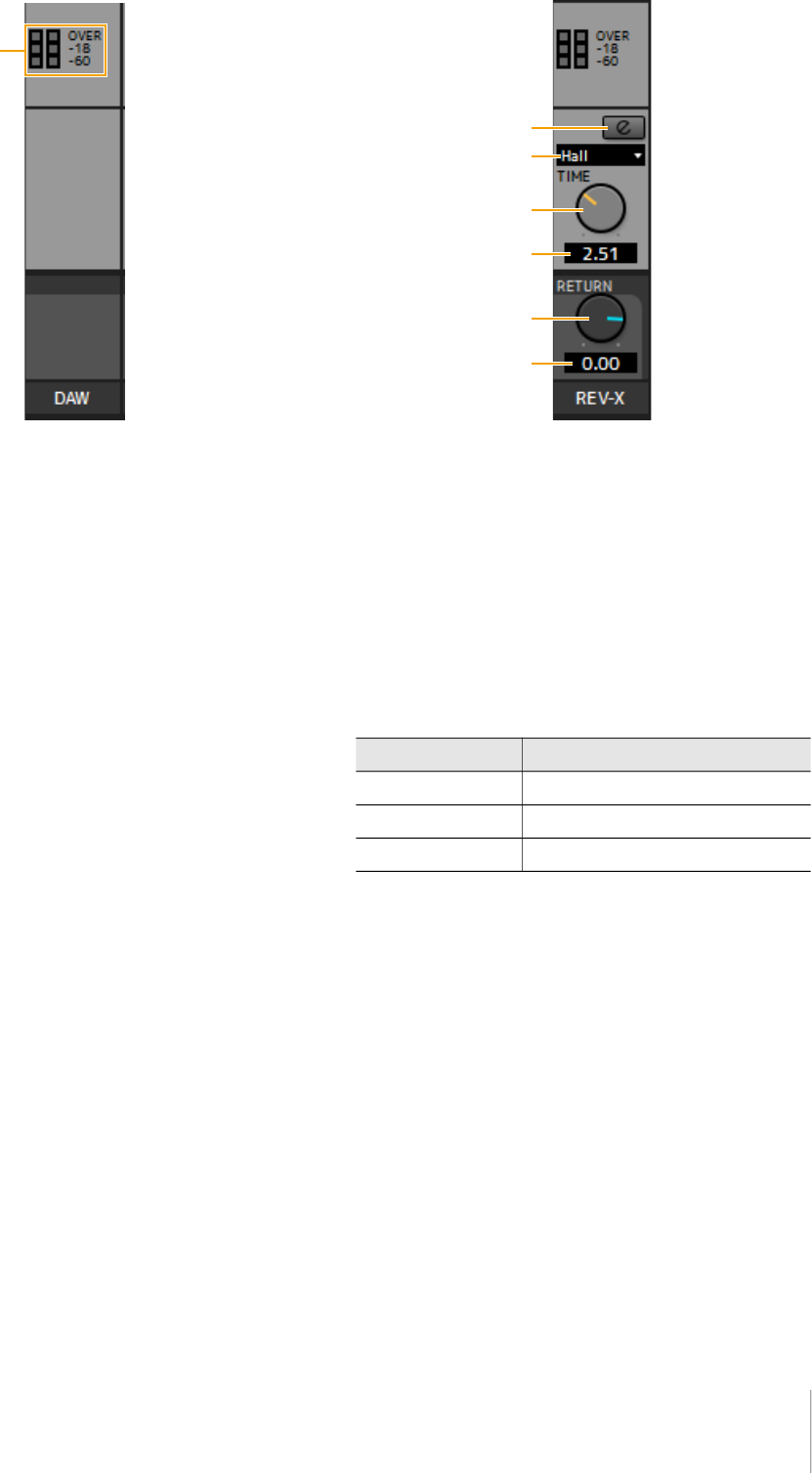
DAW Area
This is the area for configuring the DAW channel settings.
1 Level Meter
Indicates the signal level.
REV-X Area
This is the area for configuring the REV-X channel settings.
1 REV-X Edit
Opens (lit) and closes (unlit) the “REV-X” (page 18) setup
window.
2 REV-X Type
Selects the REV-X type.
Settings: Hall, Room, Plate
3 REV-X Time
Adjusts the reverb time of REV-X. This parameter links to
Room Size. The adjustable range varies depending on
REV-X type.
4 REV-X Time Value
Displays and adjusts the REV-X Time value. Enable
editing of the value by double clicking the number.
5 REV-X Return
Adjusts the return level of REV-X.
6 REV-X Return Value
Displays and adjusts the REV-X Return value. Enable
editing of the value by double clicking the number.
REV-X Type Range
Hall 0.103 sec − 31.0 sec
Room 0.152 sec − 45.3 sec
Plate 0.176 sec − 52.0 sec
Software
UR22C Operation Manual 11
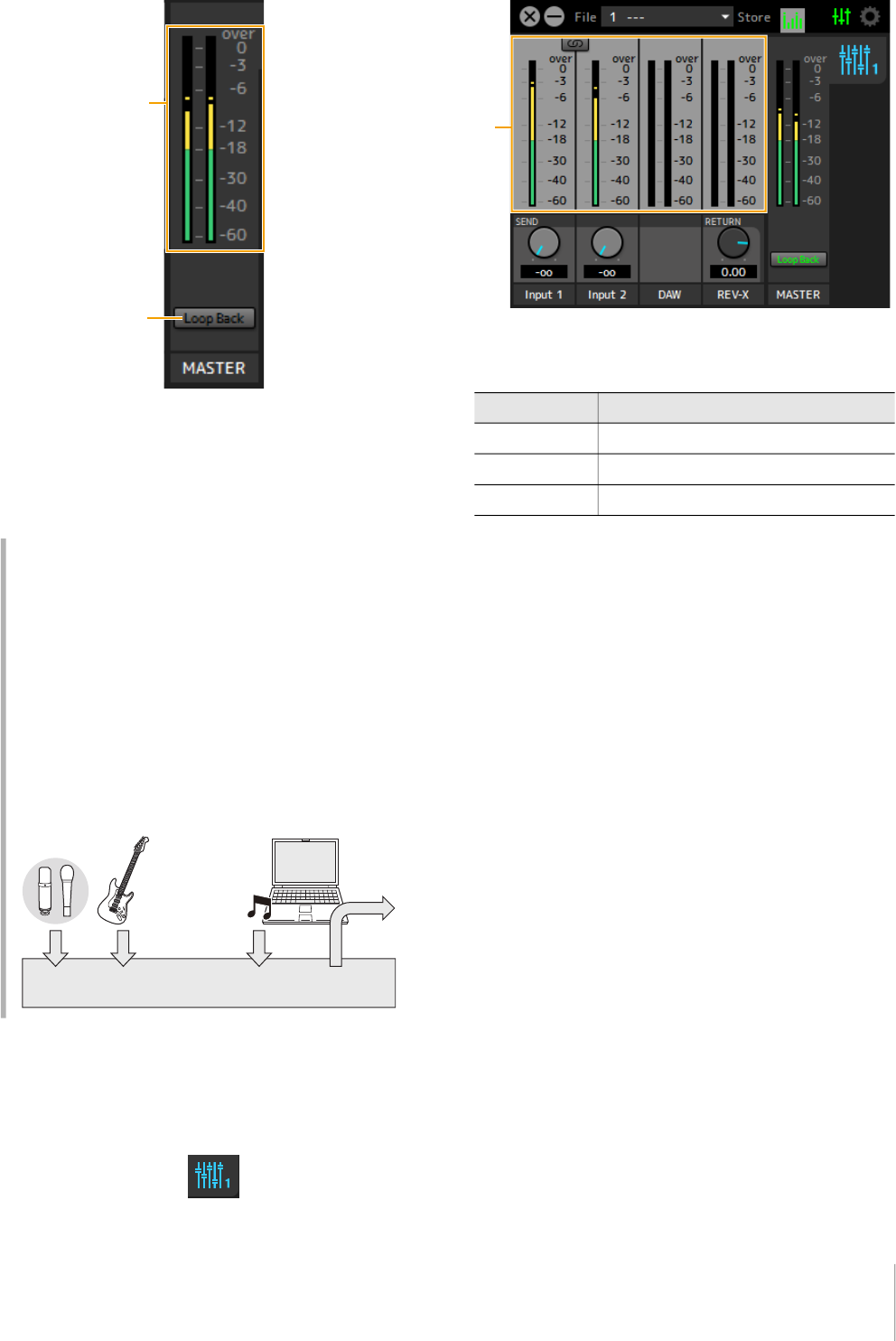
MASTER Area
This is the area for configuring the master channel
settings.
1 Level Meter
Indicates the signal level.
2 Loop Back
Turns the Loopback function on (lit) and off (unlit).
MIX Area
This is the area for selecting the MIX you want to
configure. The UR22C can be set only to MIX1.
Meter Window
This window is for showing the meter at the top of the Main
window.
1 Level Meter
Indicates the signal level. Peak hold is normally set to on.
What is Loopback?
Loopback is a convenient function for broadcasting
over the Internet. It mixes the input audio signals (such
as microphone and guitar) with the audio signals
playing back in the software in the computer into two
channels in the UR22C, and sends them back to the
computer. Refer to the section “Signal Flow” (page 34).
If the Loopback function is on while you are monitoring
input signals from the UR22C via DAW software, it will
cause loud noise. This is because an infinite loop of the
audio signal is generated between the UR22C and the
DAW software. When using the loopback function, turn
off the monitor functions on your DAW software.
UR22C
BGM
Deliver
Display color Description
Green Up to -18dB
Yellow Up to 0dB
Red CLIP
Software
UR22C Operation Manual 12
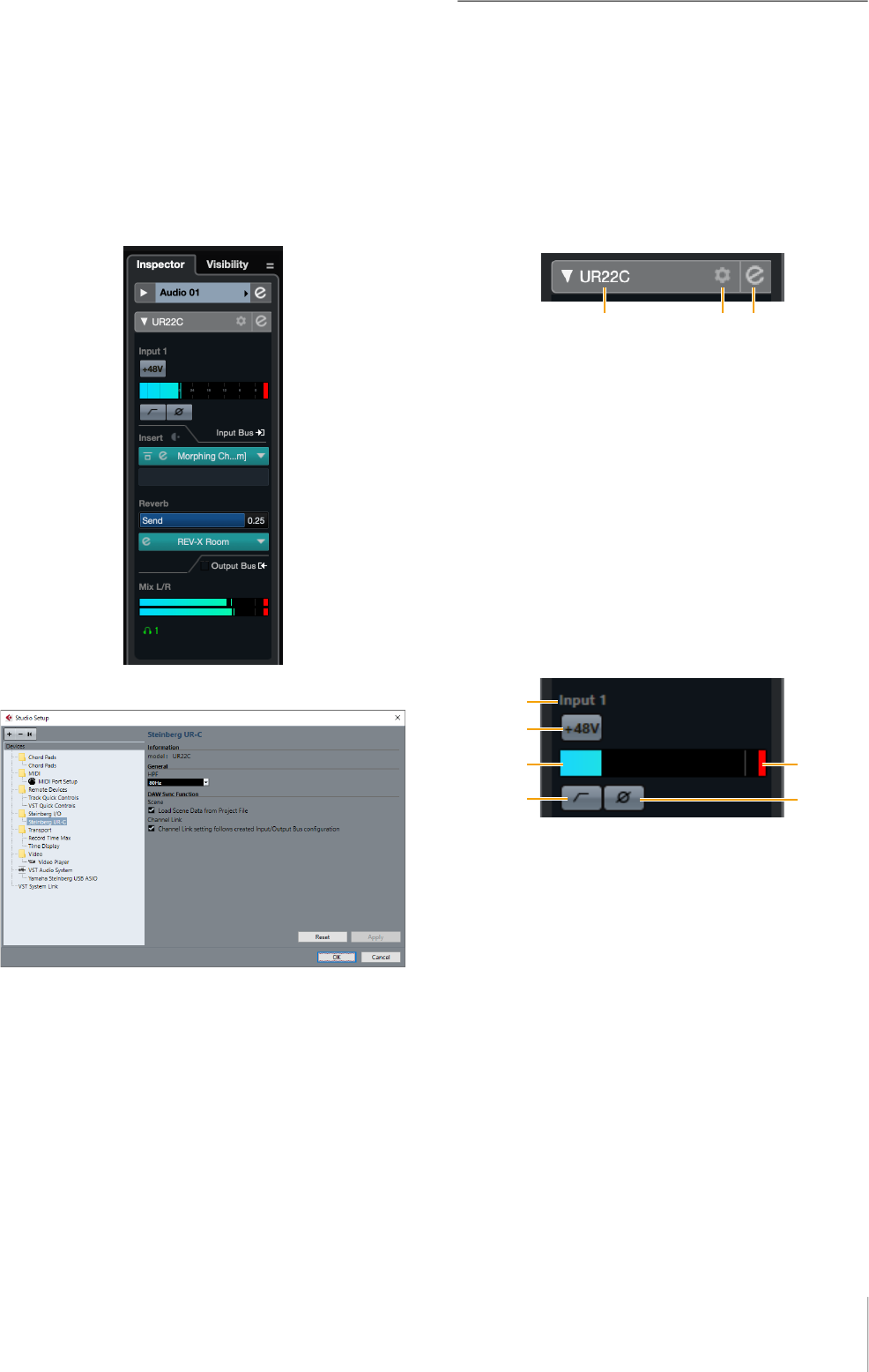
Setup Window
This window is for configuring the common settings of the
device.
1 Device
Selects the device when simultaneously connecting one
or more devices that are capable with dspMixFx.
2 Device Settings
Opens the Control Panel.
3 HPF Setting
Selects the cutoff frequency of the high pass filter.
Settings: 120 Hz, 100 Hz, 80 Hz, 60 Hz, 40 Hz
4 Zoom
Changes the window size.
Settings: 100%, 150%, 200%, 250%, 300%
5 Knob Mode
Selects the method of operating the knobs on dspMixFx
UR-C.
6 About
Indicates the version of the firmware and software.
Settings Description
Circular Drag in a circular motion to increase and
decrease the parameter. Drag on a dial
clockwise to increase, and counterclockwise to
decrease. If you click any point on the knob,
the parameter will jump there instantly.
Linear Drag in a linear motion to increase and
decrease the parameter. Drag upward or
rightward to increase, and downward or
leftward to decrease. Even if you click any point
on the knob, the parameter will not jump there.
Software
UR22C Operation Manual 13
Dedicated Windows for Cubase
Series
These are the windows for configuring the device settings
from Cubase series software. The dedicated windows for
Cubase series allow you to configure the parameters
which are configured by dspMixFx UR-C. Two types of
windows are available: Input Settings and Hardware
Setup.
Screenshot
Input Settings Window
Hardware Setup Window
How to Open the Window
Input Settings Window
From the Cubase series menu, select [Project] [Add
track] [Audio] to create an audio track and then click
the [UR22C] tab on the inspector on the left side.
Hardware Setup Window
From the Cubase series menu,
• Select [Studio] [Studio Setup], then select the
[Steinberg UR-C] on the [Steinberg I/O] on the left side.
• From Input Settings Window, click [Hardware Setup]
Input Settings Window
This window is for configuring the input settings of the
device. The signal flow is from top to bottom. The settings
on this window (except for the +48V indicator) are saved
to the Cubase project file.
The Input Settings Window is displayed on the audio track
routing as UR22C.
Header Area
Display the name of the connected device and open the
Editor.
1 model
Displays the model name (UR22C) in use. Switch between
displayed or not displayed for the Input Settings Window
by clicking it.
2 Hardware setup
Opens the Hardware Setup Window.
3 Editor Active
Opens dspMixFx UR-C.
Hardware Inputs Settings area.
This area is used to set parameters related to the UR22C
inputs.
1 Port name
Displays the name of the port which is being used for
input to the track of the device.
2 +48V
Indicates the on (lit) and off (unlit) status of the phantom
power function of the device.
3 Input meter
Displays input levels.
4 Meter Clip
Displays the input meter clip when clipping occurs. Click
this to stop this display.
5 High Pass Filter
Turns on (lit) and off (unlit) the high pass filter. To select
the cutoff frequency of the high pass filter, use the
“Hardware Setup Window” (page 15) in the section
“dspMixFx UR-C.”
Software
UR22C Operation Manual 14
6 Phase
Switches phase inversion on (lit) and off (unlit). Shows L, R
when stereo is selected.
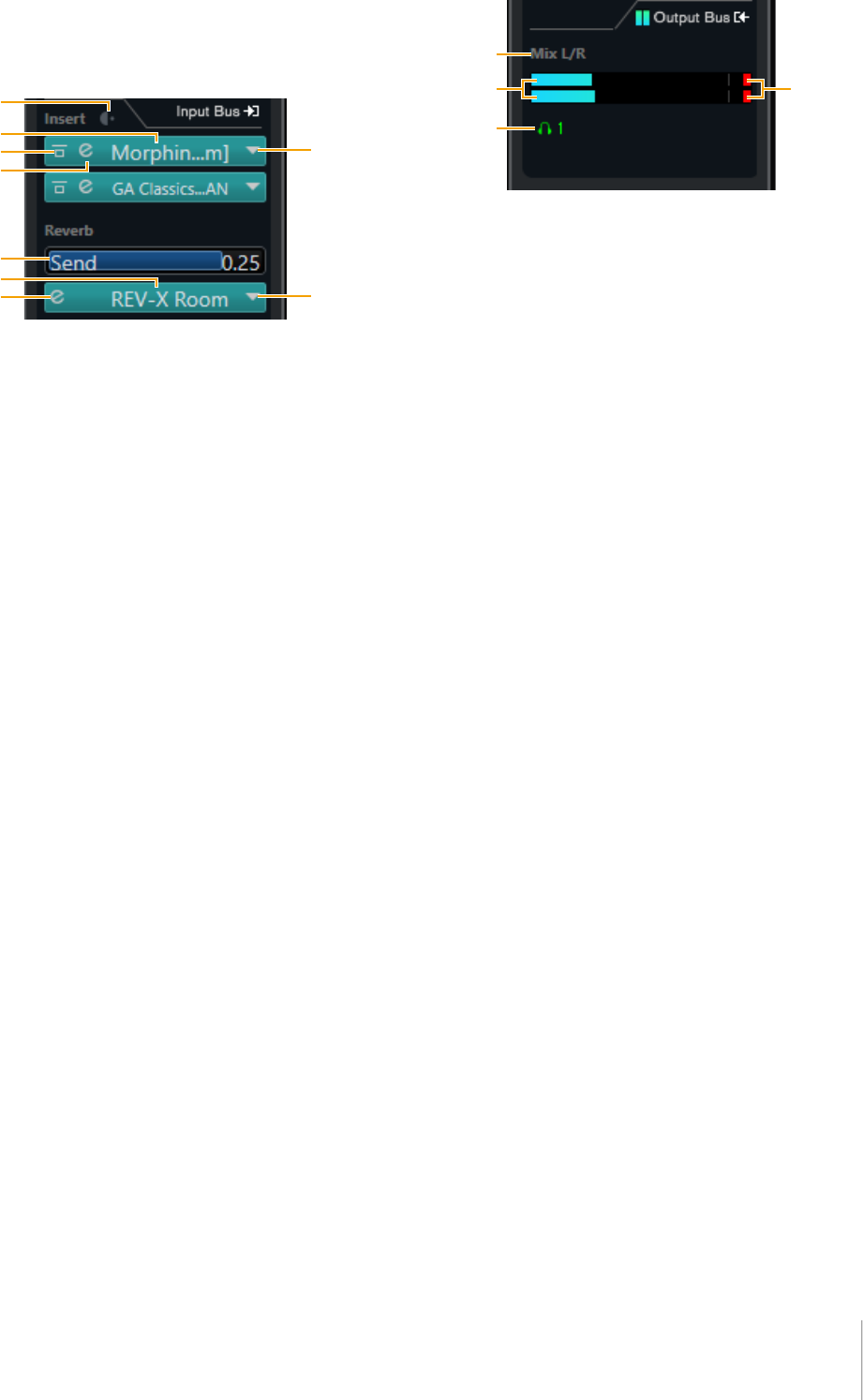
Effect Settings area
This area is used to set parameters related to the UR22C
input/output port effects.
1 Pre/Post
Used to select the insertion point for the effect.
2 Effect Name
Displays the names of the applied effects.
3 Effect Bypass
Enables/bypasses the effect.
4 Effect Edit
Displays the Effect Edit window.
5 Effect Type
Selects the effect type.
Settings: No Effect, Morphing Ch Strip ([m] or [s]), GA Classics -
CLEAN, GA Classics - CRUNCH, GA Classics - LEAD,
GA Classics - DRIVE
NOTE
The maximum number of Channel Strip and Guitar Amp Classics
iterations which can be used simultaneously is limited. Refer to
the “Limitations on the use of effects” (page 33).
6 REV-X Send
Adjusts the signal level which is sent to REV-X.
Range: -∞ dB − +6.00 dB
7 REV-X Name
Displays the selected REV-X type.
8 REV-X Edit
Opens the “REV-X” (page 18) setup window.
9 REV-X Type
Selects the REV-X type.
Settings: Hall, Room, Plate
Outputs area
This area is used to set parameters related to hardware
outputs.
1 Mix Bus name
Displays the Mix Bus name of the hardware output. The
output bus of the track must be connected to this Mix bus.
2 Output meter
Displays meters for the hardware Mix Bus connected to
hardware outputs.
3 Meter Clip
Displays the input meter clip when clipping occurs. Click
this to stop this display.
4 Headphones
The UR22C can be set only to phones1.
Software
UR22C Operation Manual 15
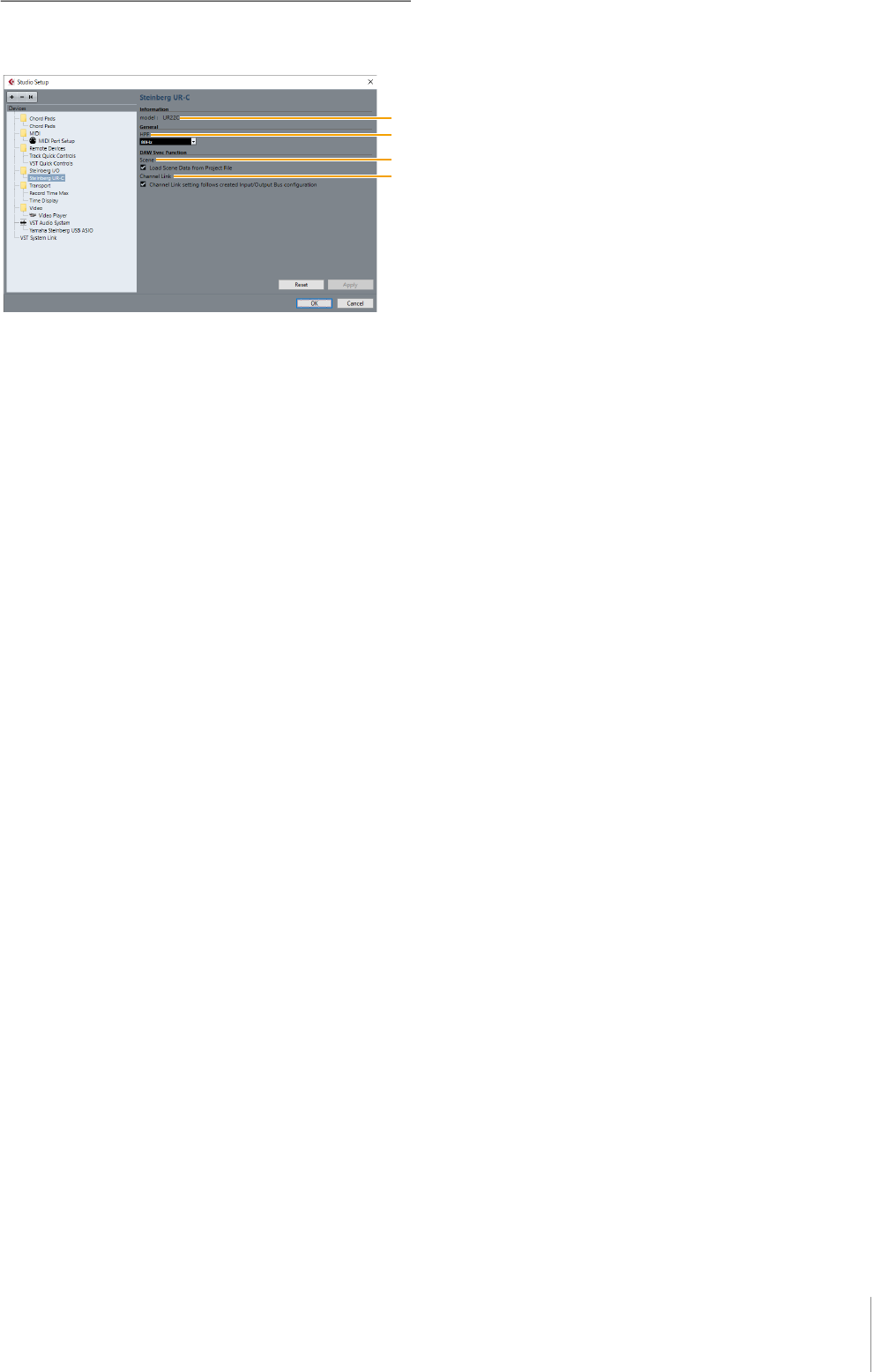
Hardware Setup Window
This window allows you to configure general hardware
settings and Cubase-linked function settings.
1 model
Displays the name of the device.
2 HPF
Selects the cutoff frequency of the high pass filter.
Settings: 120Hz, 100Hz, 80Hz, 60Hz, 40Hz
3 Scene
Automatically applies scene information to the UR22C
device when loading a Cubase project file containing
UR22C scene data.
NOTICE
Data saved to the device will be overwritten.
4 Channel Link
Automatically configures stereo links based on the bus
configuration in use.
Software
UR22C Operation Manual 16
Sweet Spot Morphing Channel
Strip
The Sweet Spot Morphing Channel Strip (“Channel Strip”
for short) is a multi-effect that combines compression and
EQ. Advanced sound engineering know-how is
condensed into a number of convenient presets that can
be simply and instantly recalled, for professional results.
Two channel strips are provided, and each can be
assigned to the monitor sound only, or to both the monitor
and recorded sound.
The Channel Strip equipped with the device and the
Channel Strip of the VST Plug-in version have the same
parameters. When using the Channel Strip on Cubase
series programs, you can share the settings between the
built-in Channel Strip and the Channel Strip of the VST
Plug-in version as a preset file. Also, when assigning the
Channel Strip of the VST Plug-in version to the effect slot
on Cubase series programs, select it from the [Dynamics]
category (in the case of the default settings).
Screenshot
How to Open the Window
From Dedicated Windows for Cubase Series
Select the “Channel Strip” from the “Effect Type”, then
click “Channel Strip Edit” in the section “Input Settings
Window” (page 14).
From dspMixFx UR-C
Select the “Channel Strip” from the “Effect Type”, then
click “Channel Strip Edit” in the section “Channel Area”
(page 9).
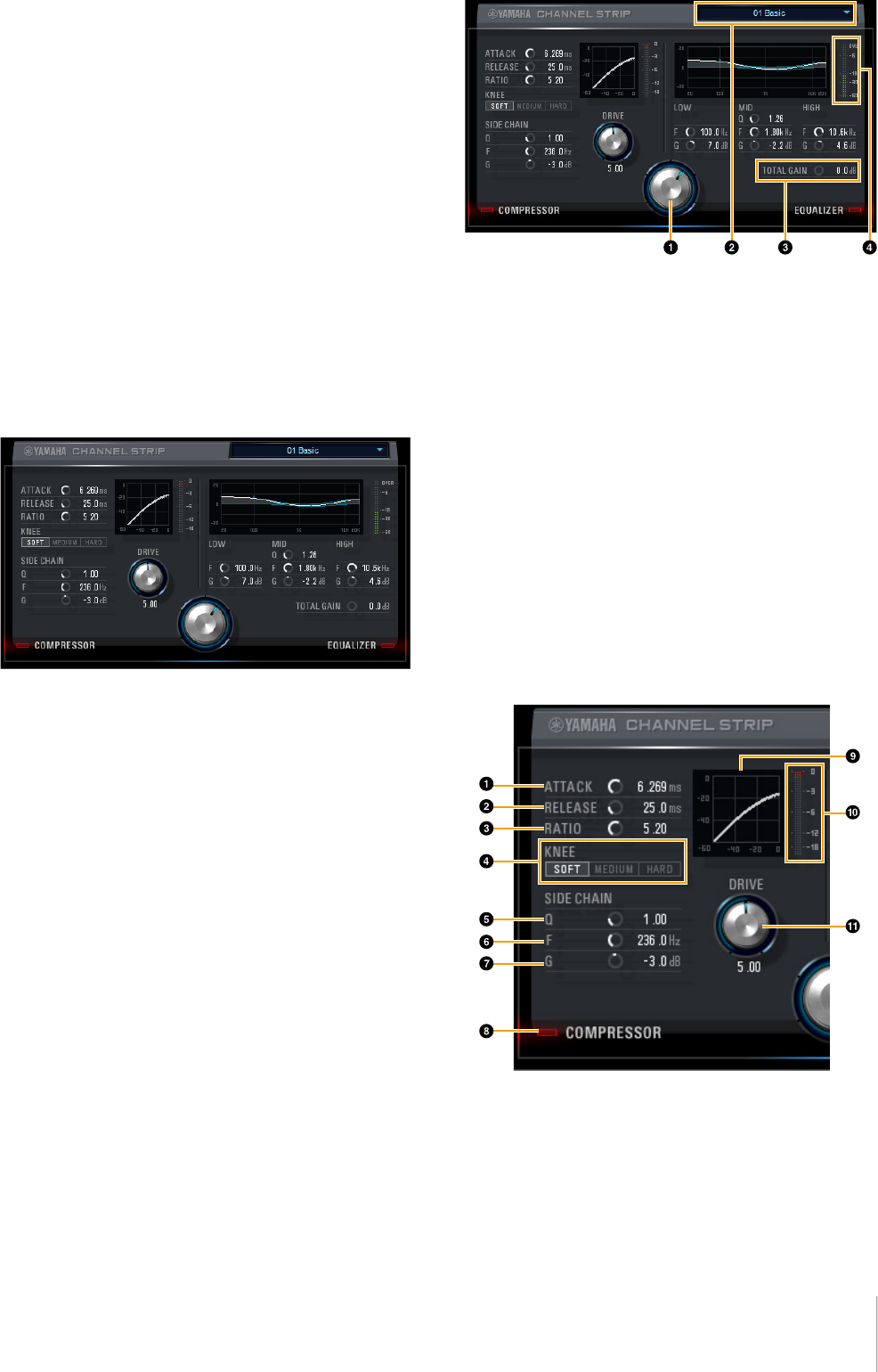
Common to Compressor and Equalizer
1 MORPH
Adjusts the parameter of the Sweet Spot Data. You can
simultaneously adjust the compressor and equalizer
settings which are set to five points around this knob by
turning this knob. When you set the knob between two
adjacent points, the compressor and equalizer settings
will be set to an intermediate value.
2 Sweet Spot Data
Selects the Sweet Spot Data.
3 TOTAL GAIN
Adjusts the total gain of the Channel Strip.
Range: -18.0 dB − +18.0 dB
4 Level Meter
Indicates the output level of the Channel Strip.
Compressor
1 ATTACK
Adjusts the attack time of the compressor.
Range: 0.092 msec − 80.00 msec
2 RELEASE
Adjusts the release time of the compressor.
Range: 9.3 msec − 999.0 msec
Software
UR22C Operation Manual 17
3 RATIO
Adjusts the release time of the compressor.
Range: 1.00 − ∞
4 KNEE
Selects the knee type of the compressor.
5 SIDE CHAIN Q
Adjusts the band width of the side chain filter.
Range: 0.50 − 16.00
6 SIDE CHAIN F
Adjusts the center frequency of the side chain filter.
Range: 20.0 Hz − 20.0 kHz
7 SIDE CHAIN G
Adjusts the gain of the side chain filter.
Range: -18.0 dB − +18.0 dB
8 COMPRESSOR On/Off
Turns the compressor on (lit) and off (unlit).
9 Compressor Curve
This graph indicates the approximate compressor
response. The vertical axis indicates the output signal
level, and the horizontal axis indicates the input signal
level.
) Gain Reduction Meter
Indicates the gain reduction.
! DRIVE
Adjusts the degree to which the compressor is applied.
The higher the value, the greater the effect.
Range: 0.00 − 10.00
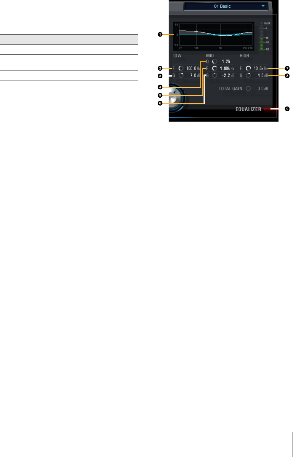
Equalizer
1 Equalizer Curve
This graph indicates the characteristics of the 3-band
equalizer. The vertical axis indicates the gain, and the
horizontal axis indicates the frequency. You can adjust
LOW, MID, and HIGH by dragging each handle in the
graph.
2 LOW F
Adjusts the center frequency of the low band.
Range: 20.0 Hz − 1.00 kHz
3 LOW G
Adjusts the gain of the low band.
Range: -18.0 dB − +18.0 dB
4 MID Q
Adjusts the band width of the middle band.
Range: 0.50 − 16.00
5 MID F
Adjusts the center frequency of the middle band.
Range: 20.0 Hz − 20.0 kHz
6 MID G
Adjusts the gain of the middle band.
Range: -18.0 dB − +18.0 dB
7 HIGH F
Adjusts the center frequency of the high band.
Range: 500.0 Hz − 20.0 kHz
8 HIGH G
Adjusts the gain of the high band.
Range: -18.0 dB − +18.0 dB
9 EQUALIZER On/Off
Turns the equalizer on (lit) and off (unlit).
Settings Description
SOFT Produces the most gradual change.
MEDIUM Results in a setting midway between
SOFT and HARD.
HARD Produces the sharpest change.
Software
UR22C Operation Manual 18
REV-X
REV-X is a digital reverb platform developed by Yamaha
for pro audio applications.
One REV-X effect is included in this unit. Input signals can
be sent to the REV-X effect, and the REV-X effect is
applied only to the monitor outputs. Three types of REV-X
are available: Hall, Room, and Plate. The hardware REV-X
equipped with the device and REV-X of the VST Plug-in
version have essentially the same parameters. However,
the [OUTPUT] and [MIX] parameters are only available in
the VST Plug-in version.
When using REV-X on Cubase series programs, you can
share the settings between the built-in REV-X and REV-X
of the VST Plug-in version as a preset file. Also, when
assigning REV-X of the VST Plug-in version to the effect
slot on Cubase series programs, select it from the
[Reverb] category (in the case of the default settings).
The built-in REV-X is equipped with an “FX Bus” which is
used for sending the signal from DAW software to REV-X.
For example, to send the recorded audio data to REV-X,
you can check the sound with REV-X, which is used for
monitoring during the recording.
Screenshot
How to Open the Window
From Dedicated Windows for Cubase Series
Click “REV-X Edit” (page 14) in the section “Reverb
Routing Window.”
From dspMixFx UR-C
Click “REV-X Edit” (page 10) in the section “REV-X Area.”
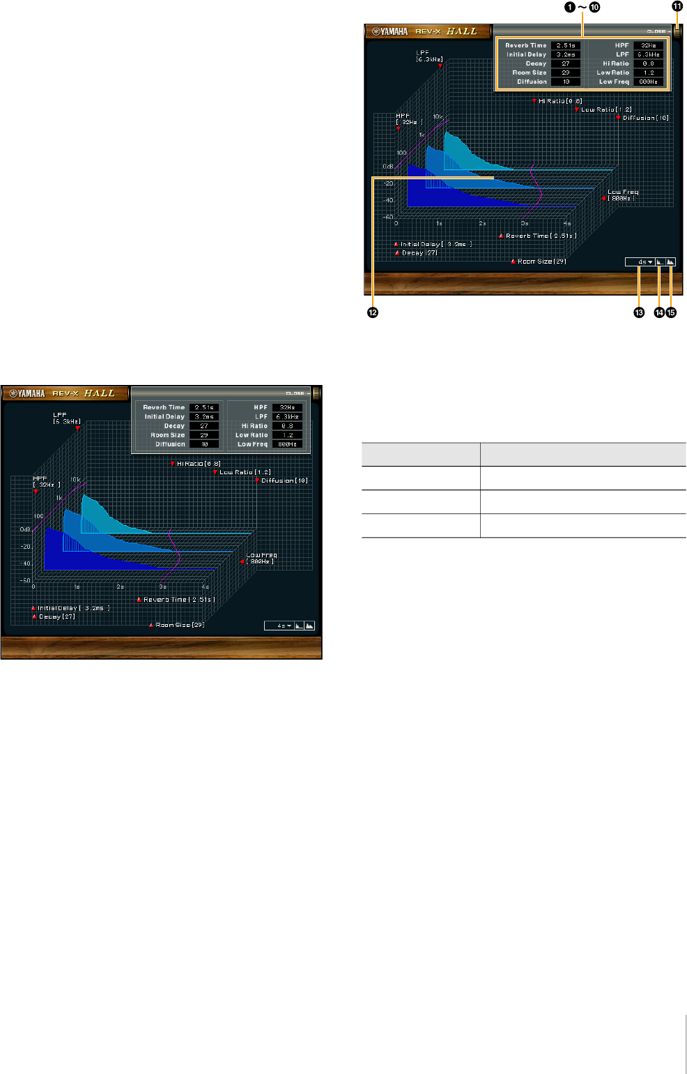
REV-X
This section uses the Hall type of REV-X as an example.
1 Reverb Time
Adjusts the reverb time. This parameter links to Room
Size. The adjustable range varies depending on the REV-
X type.
2 Initial Delay
Adjusts the time that elapses between the direct, original
sound and the initial reflections that follow it.
Range: 0.1 msec − 200.0 msec
3 Decay
Adjusts the characteristic of the envelope from the
moment the reverberation starts to the moment it
attenuates and stops.
Range: 0 − 63
4 Room Size
Adjusts the size of the simulated room. This parameter
links to Reverb Time.
Range: 0 − 31
5 Diffusion
Adjusts the spread of the reverberation.
Range: 0 − 10
6 HPF
Adjusts the cutoff frequency of the high pass filter.
Range: 20 Hz − 8.0 kHz
REV-X type Range
Hall 0.103 sec − 31.0 sec
Room 0.152 sec − 45.3 sec
Plate 0.176 sec − 52.0 sec

Software
UR22C Operation Manual 19
7 LPF
Adjusts the cutoff frequency of the low pass filter.
Range: 1.0 kHz − 20.0 kHz
8 Hi Ratio
Adjusts the duration of reverberation in the high frequency
range by using a ratio relative to the Reverb Time. When
you set this parameter to 1, the actual specified Reverb
Time is fully applied to the sound. The lower the value, the
shorter the duration of reverberation in the high frequency
range.
Range: 0.1 − 1.0
9 Low Ratio
Adjusts the duration of reverberation in the low frequency
range by using a ratio relative to the Reverb Time. When
you set this parameter to 1, the actual specified Reverb
Time is fully applied to the sound. The lower the value, the
shorter the duration of reverberation in the low frequency
range.
Range: 0.1 − 1.4
) Low Freq
Adjusts the frequency of the Low Ratio.
Range: 22.0 Hz − 18.0 kHz
! OPEN/CLOSE
Opens and closes the window for adjusting the reverb
settings.
@ Graph
Indicates the characteristics of reverberation. The vertical
axis indicates the signal level, the horizontal axis indicates
the time, and the Z-axis indicates the frequency. You can
adjust the characteristics of reverberation by dragging the
handles in the graph.
# Time Axis Setting
Select the display range of the time (horizontal axis) on
the graph.
Display range: 500 msec − 50 sec
$ Zoom Out
Zooms out the display range of the time (horizontal axis)
on the graph.
% Zoom In
Zooms in the display range of the time (horizontal axis) on
the graph.
Software operation
• You can reset certain parameters to their default
values by holding the [Ctrl]/[command] key while you
click on the appropriate knobs, sliders, and faders.
• You can adjust the parameters more finely by holding
the [SHIFT] key while you drag on the appropriate
knobs, sliders, and faders.
Software
UR22C Operation Manual 20
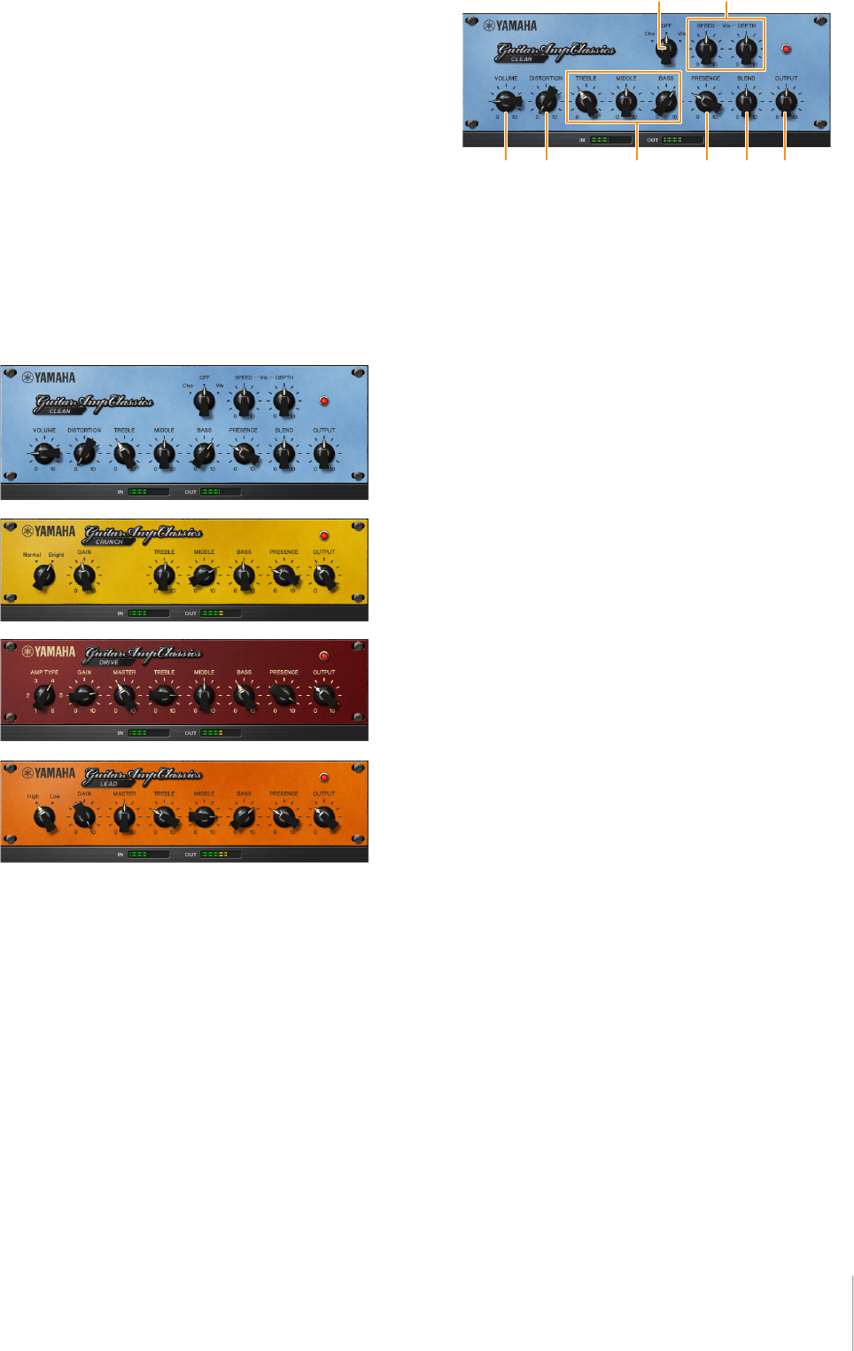
Guitar Amp Classics
Guitar Amp Classics are guitar amp simulations that make
extensive use of advanced Yamaha modeling technology.
Four amp types with different sonic characteristics are
provided.
The Guitar Amp Classics equipped with the device and
the Guitar Amp Classics of the VST Plug-in version have
the same parameters. When using the Guitar Amp
Classics on Cubase series programs, you can share the
settings between the built-in Guitar Amp Classics and the
Guitar Amp Classics of the VST Plug-in version as a
preset file. Also, when assigning the Guitar Amp Classics
of the VST Plug-in version to the effect slot on Cubase
series programs, select it from the [Distortion] category (in
the case of the default settings). Note that Guitar Amp
Classics equipped with the device cannot be used when
the sample rate is set to 176.4 kHz or 192 kHz.
Screenshot
How to Open the Window
From Dedicated Windows for Cubase Series
Select the “Guitar Amp Classics” from the “Effect Type”,
then click “Effect Edit” in the section “Input Settings
Window” (page 14).
From dspMixFx UR-C
Select the “Guitar Amp Classics” from the “Effect Type”,
then click “Effect Edit” in the section “Channel Area”
(page 9).
CLEAN
This amp type is optimized for clean tones, effectively
simulating the tight brilliance of transistor amplifiers. The
tonal character of this amp model provides an ideal
platform for recording with multi-effects. It also features
built-in chorus and vibrato effects.
1 VOLUME
Adjusts the amplifier’s input level.
2 DISTORTION
Adjusts the depth of distortion produced.
3 TREBLE/MIDDLE/BASS
These three controls adjusts the amplifier’s tonal response
in the high, middle, and low frequency ranges.
4 PRESENCE
Can be adjusted to emphasize the high frequencies and
overtones.
5 Cho/OFF/Vib
Turns the Chorus or Vibrato effect on or off. Set to [Cho] to
turn the Chorus effect on, or to [Vib] to turn the Vibrato
effect on.
6 SPEED/DEPTH
These controls adjust the speed and depth of the Vibrato
effect when it is on. The SPEED and DEPTH controls only
work with the Vibrato effect, and are disengaged when the
Cho/OFF/Vib control, above, is set to “Cho” or “OFF.”
7 BLEND
Adjusts the balance between the direct and effect sound.
8 OUTPUT
Adjusts the final output level.
Software
UR22C Operation Manual 21
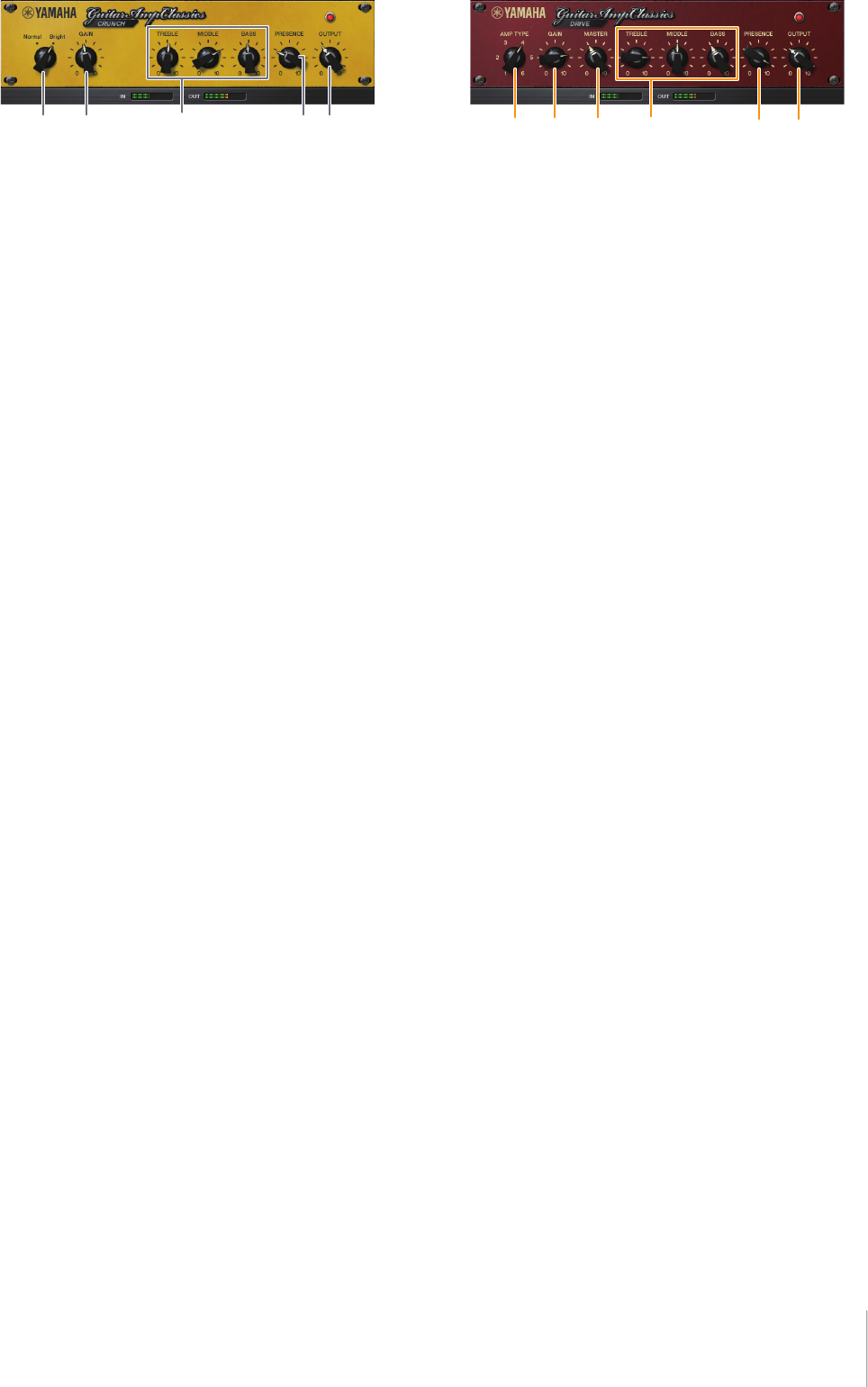
CRUNCH
This is the amp type to use when you want lightly
overdriven crunch tones. The CRUNCH model simulates
the type of vintage tube amplifiers that are favored for
blues, rock, soul, R&B, and similar styles.
1 Normal/Bright
Selects a normal or bright tonal character. The [Bright]
setting emphasizes the high-frequency overtones.
2 GAIN
Adjusts the input level applied to the preamp stage.
Rotate clockwise to increase the amount of overdrive
produced.
3 TREBLE/MIDDLE/BASS
These three controls adjust the amplifier’s tonal response
in the high, middle, and low frequency ranges.
4 PRESENCE
Can be adjusted to emphasize the high frequencies and
overtones.
5 OUTPUT
Adjusts the final output level.
DRIVE
The DRIVE amp type provides a selection of distortion
sounds that simulate the tonal character of various high
gain tube amplifiers. From mildly overdriven crunch to
heavy distortion suitable for hard rock, heavy metal, or
hardcore styles, this model offers a wide range of sonic
capabilities.
1 AMP TYPE
Six amplifier types are provided. Types 1 and 2 feature
relatively mild distortion that allows picking nuances to
come through naturally. Types 3 and 4 have more
pronounced overtones, resulting in a fat, soft tone. Types
5 and 6 deliver wilder, aggressive distortion with a tight
attack. The even-numbered amp types have greater
presence and range than the odd-numbered types.
2 GAIN
Adjusts the input level applied to the preamp stage.
Rotate clockwise to increase the amount of distortion
produced.
3 MASTER
Adjusts the output level from the preamp stage.
4 TREBLE/MIDDLE/BASS
These three controls adjust the amplifier’s tonal response
in the high, middle, and low frequency ranges.
5 PRESENCE
Can be adjusted to emphasize the high frequencies and
overtones.
6 OUTPUT
Adjusts the final output level.
Software
UR22C Operation Manual 22
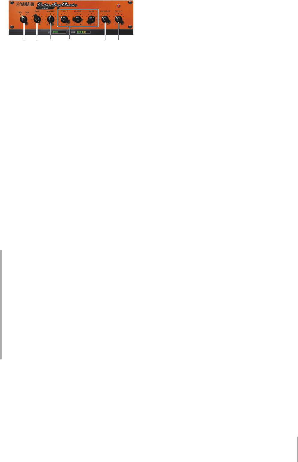
LEAD
The LEAD amp type simulates a high-gain tube amp that
is rich in overtones. It is ideally suited to playing lead
guitar lines that will project well in an ensemble, but it can
also be set up for crisp accompaniment tones as well.
1 High/Low
Selects the amp output type. The [High] setting simulates
a high-output amp, and allows the creation of more
distorted tones.
2 GAIN
Adjusts the input level applied to the preamp stage.
Rotate clockwise to increase the amount of distortion
produced.
3 MASTER
Adjusts the output level from the preamp stage.
4 TREBLE/MIDDLE/BASS
These three controls adjust the amplifier’s tonal response
in the high, middle, and low frequency ranges.
5 PRESENCE
Used to emphasize the high frequencies and overtones.
6 OUTPUT
Adjusts the final output level.
Using the GAIN, MASTER, and OUTPUT
Controls
The tonal character of the DRIVE and LEAD amp types
can be adjusted over a wide range via the GAIN,
MASTER, and OUTPUT controls. GAIN adjusts the level
of the signal applied to the preamp stage, affecting the
amount of distortion produced. MASTER adjusts the
output level from the preamp stage that is then fed to
power amp stage. The GAIN and MASTER control
settings have a large effect on the final sound, and the
MASTER control may need to be turned up fairly high in
order to drive the power stage sufficiently for optimum
tone. The OUTPUT control adjusts the final output level
from the amp model without affecting the distortion or
tone, and is useful for adjusting the guitar’s volume
without changing any other aspects of the sound.
Using with a Computer
UR22C Operation Manual 23
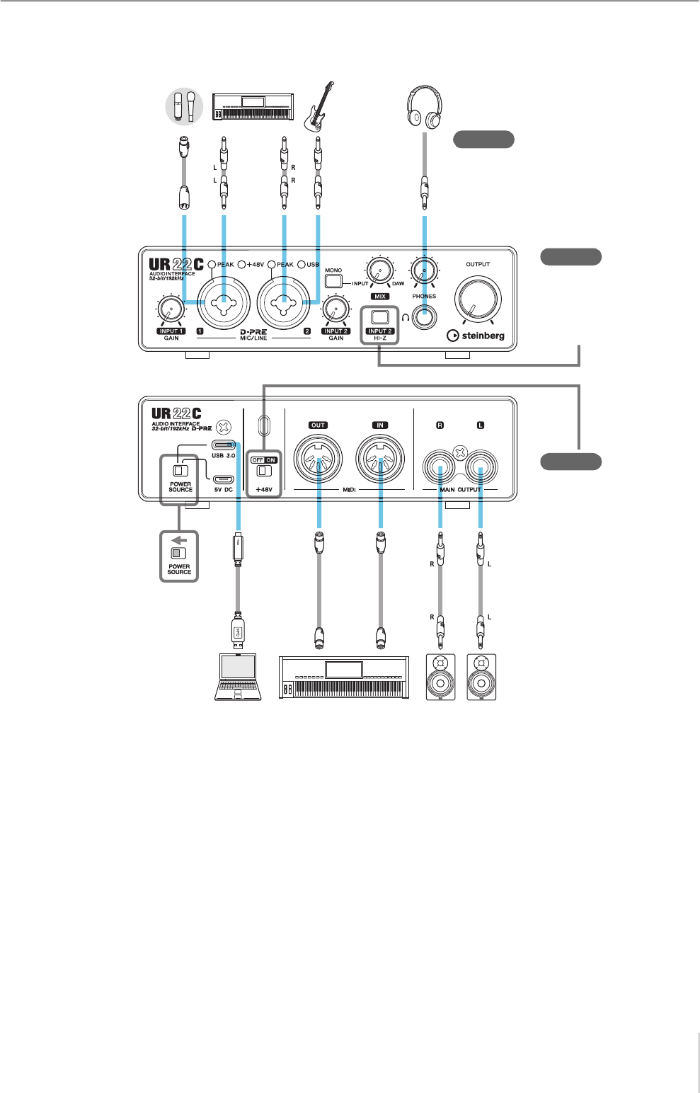
Using with a Computer
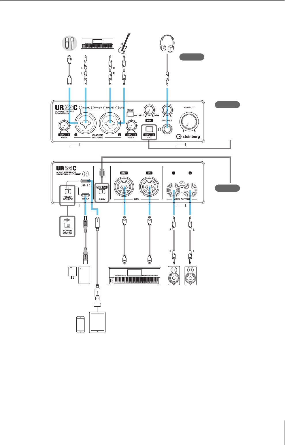
Connection Example
NOTE
• When using the device with bus power supply, connect it to the USB 3.0 port of the computer.
• For the connector type of the computer to be connected to the device, refer to “Connector type of a computer” (page 33).
Microphone GuitarKeyboard Headphones
Front panel
Rear panel
When using the condenser
microphone, turn the switch
on after connecting it.
(Turn the switch off before
disconnecting it.)
Check!
Check!
Set all volume levels to
minimum before connecting
or disconnecting the
external device.
Computer Synthesizer/MIDI keyboard Monitor
speakers
When connecting an electric
guitar or electric bass, turn the
switch on after connecting the
instrument. (Turn the switch off
before disconnecting it.)
Check!

Using with a Computer
UR22C Operation Manual 24
Configuring Audio Driver Settings
on the DAW Software
Cubase Series Programs
1.
Make sure that all applications have been
closed.
2. Connect the device directly to the computer
by using the included USB cable.
3. Confirm the [USB] indicator is lit.
4. Double-click the shortcut of Cubase series
on the desktop to start Cubase.
5. When the [ASIO Driver Setup] window
appears while the Cubase series program is
launching, confirm that the device is
selected, then click [OK].
NOTE
When [Steinberg UR22C (High Precision)] is selected on
Mac, Cubase will exclusively uses the driver. In this
condition, [Steinberg UR22C] cannot be used by other
applications.
The audio driver settings are now complete.
Programs other than Cubase Series
1.
Make sure that all applications have been
closed.
2. Connect the device directly to the computer
by using the included USB cable.
3. Confirm the [USB] indicator is lit.
4. Launch the DAW software.
5. Open the audio interface settings window.
6. (Windows only) Select the ASIO Driver for
the audio driver settings.
7. Set the ASIO Driver for Windows and audio
interface for Mac as follows.
Windows
Set the [Yamaha Steinberg USB ASIO] to the ASIO
Driver settings.
Mac
Set the UR22C to the audio interface settings.
The audio driver settings are now complete.
Using with a Computer
UR22C Operation Manual 25
Recording/Playback
This section explains simple recording operations for
using a microphone. Connect a microphone to [MIC/LINE
1] jack as shown in the connection examples (page 23).
Turn the [+48V] switch on when using a phantom powered
condenser microphone.
Cubase Series Programs
1.
Launch the Cubase series DAW and display
the [steinberg hub] window.
2. Select the template [Empty] in [Recording]
on the [steinberg hub] window, then click
[Create].
3. Turn on Direct Monitoring as follows.
[Studio] [Studio Setup] [Yamaha Steinberg
USB ASIO] (Windows) or [Steinberg UR22C] (Mac)
enter checkmark to [Direct Monitoring] [OK]
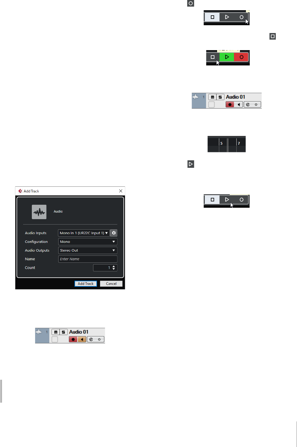
4. Return to the project window and click
[Project] [Add Track] [Audio] to display
[Add Track].
5. Select the [Audio Inputs] and
[Configuration] to [Mono] and [Count] to [1],
and then click [Add track] to create one new
audio track.
6. Confirm that the [Record Enable] and
[Monitor] indicators are turned on (lit) for the
added audio track.
7. While singing into the microphone, adjust
the input signal level of the microphone with
the [INPUT 1 GAIN] knob on the device.
8. While singing into the microphone, adjust
the output signal level of the headphones
with the [PHONES] knob on the device.
9. Click to start the recording.
10. After finishing the recording, click to
stop it.
11. Turn [Monitor] off (unlit) for the just
recorded audio track.
12. Click the Ruler to move the project cursor to
the desired point for starting playback.
13. Click to check the recorded sound.
When listening to the sound over monitor speakers,
adjust the output signal level by the [OUTPUT] knob
on the device.
The recording and playback operations are now
complete.
For more detailed instructions on using Cubase series
programs, refer to the Cubase operation manual.
Setting optimum recording levels
Adjust the [INPUT GAIN] knobs so that the [PEAK]
indicator flashes briefly at the loudest input volume.

Using with a Computer
UR22C Operation Manual 26
Programs other than Cubase Series
1.
Launch your DAW software.
2. Open dspMixFx UR-C.
For instructions on how to open dspMixFx UR-C,
refer to the section “How to Open the Window”
(page 8).
3. Adjust the input signal level of the
microphone with the [INPUT GAIN] knob on
the device.
4. While singing into the microphone, adjust
the output signal level of the headphones
with the [PHONES] knob on the device.
5. Set the Channel Strip settings and REV-X
settings on dspMixFx UR-C.
6. Start recording on your DAW software.
7. After finishing recording, stop it.
8. Playback the newly recorded sound to
check it.
For more detailed instructions on using the DAW software,
refer to your particular DAW’s software manual.
Setting optimum recording levels
Adjust the [INPUT GAIN] knobs so that the [PEAK]
indicator flashes briefly at the loudest input volume.
Using with an iOS Device
UR22C Operation Manual 27
Using with an iOS Device
Connection Example
NOTE
• Apple accessories may be required when connecting the UR22C with iOS devices. For details, refer to the UR22C Startup Guide.
• For iOS devices, it is necessary to supply power from the USB power adapter or a USB mobile battery.
• For the latest information on compatible iOS devices, refer to the Steinberg website below.
https://www.steinberg.net/
iPadiPhone
Microphone GuitarKeyboard Headphones
Front panel
Rear panel
When using the condenser
microphone, turn the switch
on after connecting it.
(Turn the switch off before
disconnecting it.)
Check!
Check!
Set all volume levels to
minimum before connecting
or disconnecting the
external device.
Synthesizer/MIDI keyboard Monitor
speakers
When connecting an electric
guitar or electric bass, turn the
switch on after connecting the
instrument. (Turn the switch off
before disconnecting it.)
Check!
USB adapter/
USB mobile battery
Using with an iOS Device
UR22C Operation Manual 28
Recording/Playback
This section explains simple recording operations for
using a microphone. Connect a microphone to [MIC/LINE
1] jack as shown in the connection examples (page 27).
Turn the [+48V] switch on when using a phantom powered
condenser microphone.
The explanation uses Cubasis (DAW app) as an example.
NOTE
• iOS app may not be supported in your area. Please check with
your Yamaha dealer.
• For the latest Cubasis information, see the Steinberg web site
below.
https://www.steinberg.net/
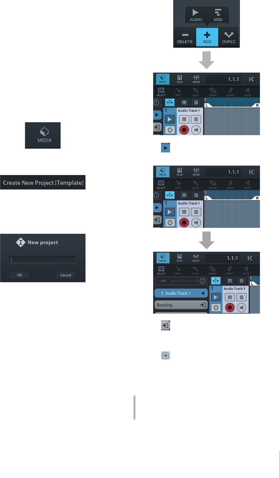
1. Open Cubasis.
2. Tap the [MEDIA] tab on the upper left of the
screen.
[Create New Project] is shown in the bottom of the
screen.
3. Tap the [Create New Project].
4. Enter a project name and tap [OK] in the
[New project] window.
5. Tap [+ADD] on the left of the screen, then
tap [AUDIO] to add an Audio Track.
6. Tap on the far left of your screen to
show the track inspector.
7. Tap to show the details window and set
the input bus for the track by tapping a
number.
8. Tap to turn monitoring on (lit).
9. Adjust the input signal level of the
microphone with the [INPUT 1 GAIN] knob
on the device.
Setting optimum recording levels
Adjust the [INPUT GAIN] knobs so that the [PEAK]
indicator flashes briefly at the loudest input volume.
Using with an iOS Device
UR22C Operation Manual 29
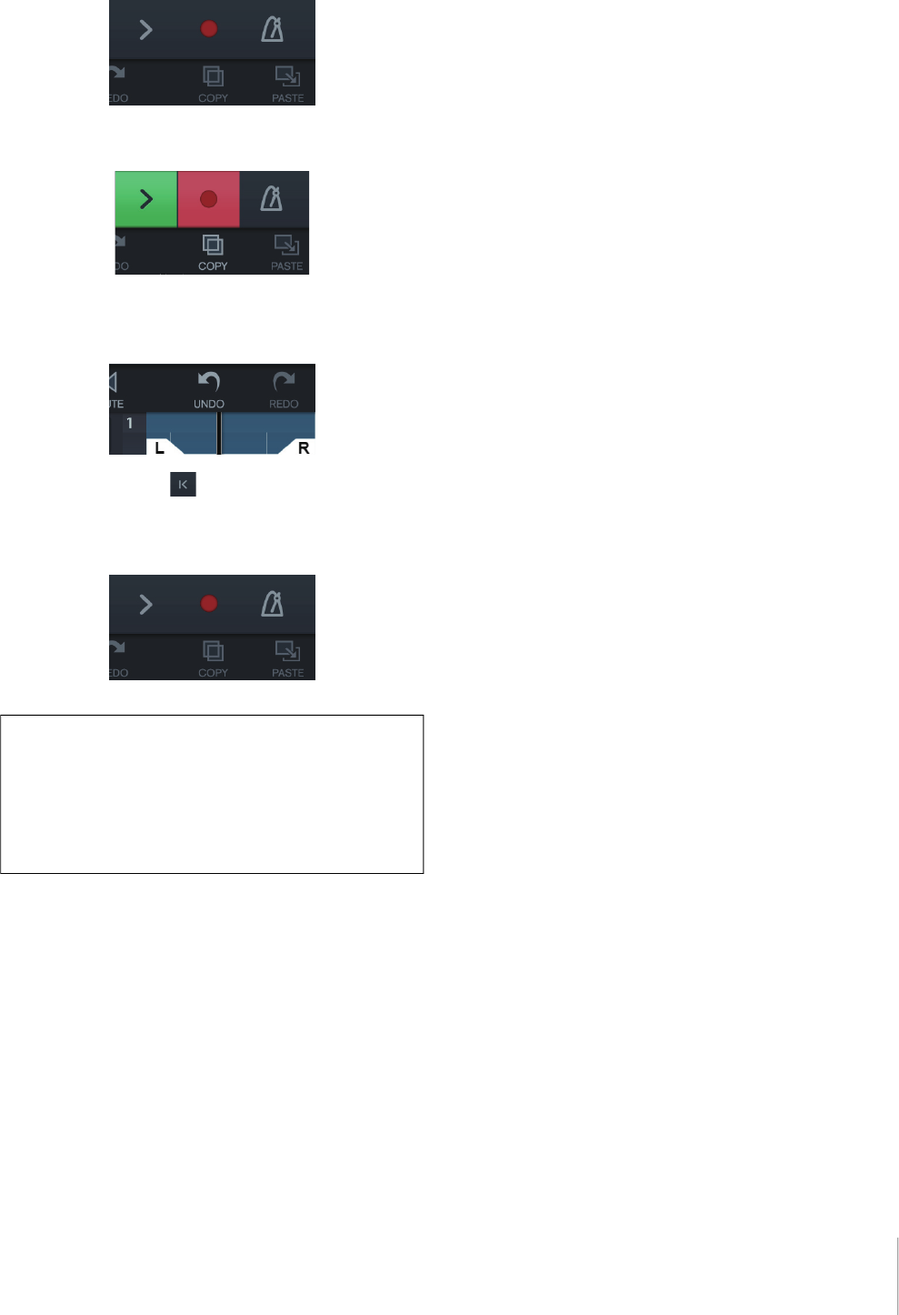
10. While singing into the microphone, adjust
the output signal level of the headphones
with the [PHONES] knob on the device.
11. Tap [
I
] to start the recording.
12. Tap [>] to stop the recording.
13. Tap and slide on the ruler to move the
playback position.
You can also tap to return the beginning of the
recording.
14. Tap [>] to playback the recorded sound.
dspMixFx (for iOS devices)
From your iOS devices, you can conveniently control
built-in DSP mixer functions and DSP effects by using
dspMixFx for iOS devices. For details on this app, see
the Steinberg web site below.
https://www.steinberg.net/
Troubleshooting
UR22C Operation Manual 30
Troubleshooting
The power indicator is off
Is the [POWER SOURCE] switch set properly?
The power indicator does not light when power is not supplied to the device.
Move the [POWER SOURCE] switch to the [5V DC] jack side when using AC
adapter or move the switch to [USB 3.0] jack side for bus-powered supply
(computer only).
The power indicator
flashes continuously
Is there a problem with power supply?
The indicator flashes continuously If the power supply is insufficient. Move the
[POWER SOURCE] switch to [5V DC] jack side and use the USB power adaptor
or USB mobile battery for the power supply.
Confirm whether or not a proper USB cable is used.
• Make sure to use the included USB cable.
• For a connecting the device to the USB Type-C port of a computer, use a
commercially available USB 3.1 Type -C to Type-C cable.
The USB indicator flashes
continuously
Has TOOLS for UR-C been installed properly? (Computer only)
The indicator flashes continuously when the computer or iOS device does not
recognize the device. Refer to the Startup Guide instructions to complete the
TOOLS for UR-C installation.
No Sound
Has TOOLS for UR-C been installed properly? (Computer only)
Refer to the Startup Guide instructions to complete the TOOLS for UR-C
installation.
Confirm that a proper USB cable is being used.
Make sure to use the included USB cable.
Are the volume controls of the device set to appropriate levels?
Confirm the levels of the [OUTPUT] knob and [PHONES] knob.
Are the microphones and monitor speakers connected to the
device properly?
Refer to the section “Connection Examples” (pages 23, 27) to confirm the
connection.
Are the audio driver settings on DAW software set properly?
Refer to the section “Configuring the Audio Driver Settings on DAW Software”
(page 24) to set it.
Troubleshooting
UR22C Operation Manual 31
No Sound
Is the [ASIO Driver] setting on the Cubase series program set
properly?
From the Cubase series menu, open the [Studio] [Studio Setup] [VST Audio
System], then confirm that the [Yamaha Steinberg USB ASIO] (Windows) or
[Steinberg UR22C] or [Steinberg UR22C (High Precision)] (Mac) is selected on
the [ASIO Driver].
Was the power of the device turned on before starting the DAW
software?
Before starting the DAW software, connect the device to a computer and turn on
the power of the device.
Is the input/output routing set properly?
Refer to the section “Recording/Playback” (page 25) to check the input/output
routing in the DAW.
Is the monitor speaker switch turned on?
Confirm that the monitor speaker switch is turned on.
Is the buffer size set too low?
Increase the buffer size compared to the current settings; refer to the section
“Yamaha Steinberg USB Driver” (page 6) for instructions.
Is the error message “Audio Format is Unmixable” shown? (Mac
only)
The error message “Audio Format is Unmixable” is shown in the Yamaha
Steinberg USB control panel. Click [Revert to Mixable] to resolve the error.
Windows Mac

Troubleshooting
UR22C Operation Manual 32
For the latest support information, refer to the Steinberg website below.
https://www.steinberg.net/
Unusual sound
(noise, interruption, or distortion)
Does your computer satisfy the system requirements?
Confirm the system requirements. For the latest information, see the Steinberg
website below.
https://www.steinberg.net/
Is the USB Mode set properly?
Depending on the USB host controller in your computer, audio dropout might
occur when SuperSpeed (USB 3.1 Gen1) mode is used. In such a case, please
try switching to High-Speed (USB 2.0) mode in the Yamaha Steinberg USB
Driver Control Panel.
Are you recording or playing long continuous sections of audio?
The audio data processing capabilities of your computer will depend on a
number of factors including CPU speed and access to external devices. Reduce
the audio tracks and check the sound again.
Are the microphones properly connected to the device?
Connect a microphone with an XLR plug to the device. If you use a phone plug,
the volume may be insufficient.
Is the loopback function set properly?
Set Enable Loopback to off when not using the Loopback function. For
instructions, refer to the section “Settings Window” (page 11).
Is the error message “Audio Format is Unmixable” shown? (Mac
only)
The error message “Audio Format is Unmixable” is shown in the Yamaha
Steinberg USB control panel. Click [Revert to Mixable] to resolve the error.
Appendix
UR22C Operation Manual 33
Appendix
Limitations on the use of effects
Two Channel Strips and one Guitar Amp Classics are
provided in the UR22C.
Simultaneous use of the Channel Strips and Guitar Amp
Classics on the same channel is possible since two slots
are provided for inserting effects in to each input channel.
However, the following restrictions apply.
• Two Channel Strips and two Guitar Amp Classics
cannot be used in the same channel.
• Guitar Amp Classics cannot be used in stereo
channels.
• Guitar Amp Classics cannot be used when the sample
rate is set to 176.4 kHz or 192 kHz.
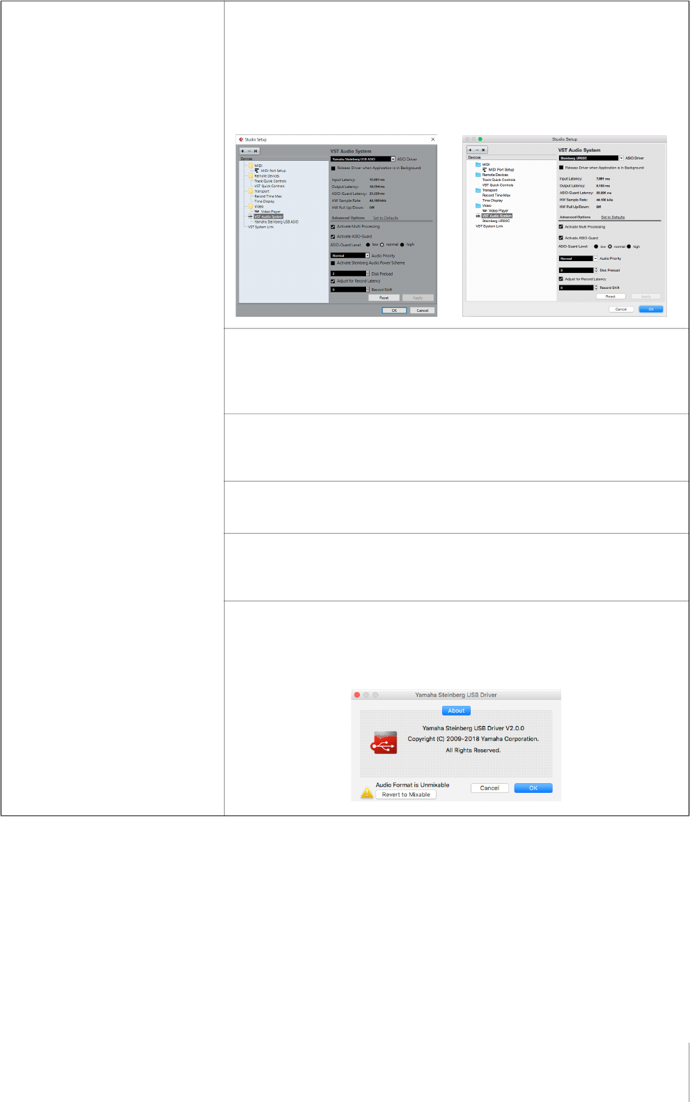
Computer connector types
USB 3.0 Type A
When connecting the device to a USB 3.0 Type-A port of
the computer, you will need the included USB cable.
USB 2.0 Type A
When connecting the device to a USB 2.0 Type-A port of
the computer, you will need the included USB cable and a
commercially available USB power adapter or USB mobile
battery.
USB 3.1 Type C
When connecting the device to a USB 3.1 Type C port,
you will need a commercially available USB 3.1 Type-C to
Type-C cable (optional).
Appendix
UR22C Operation Manual 34
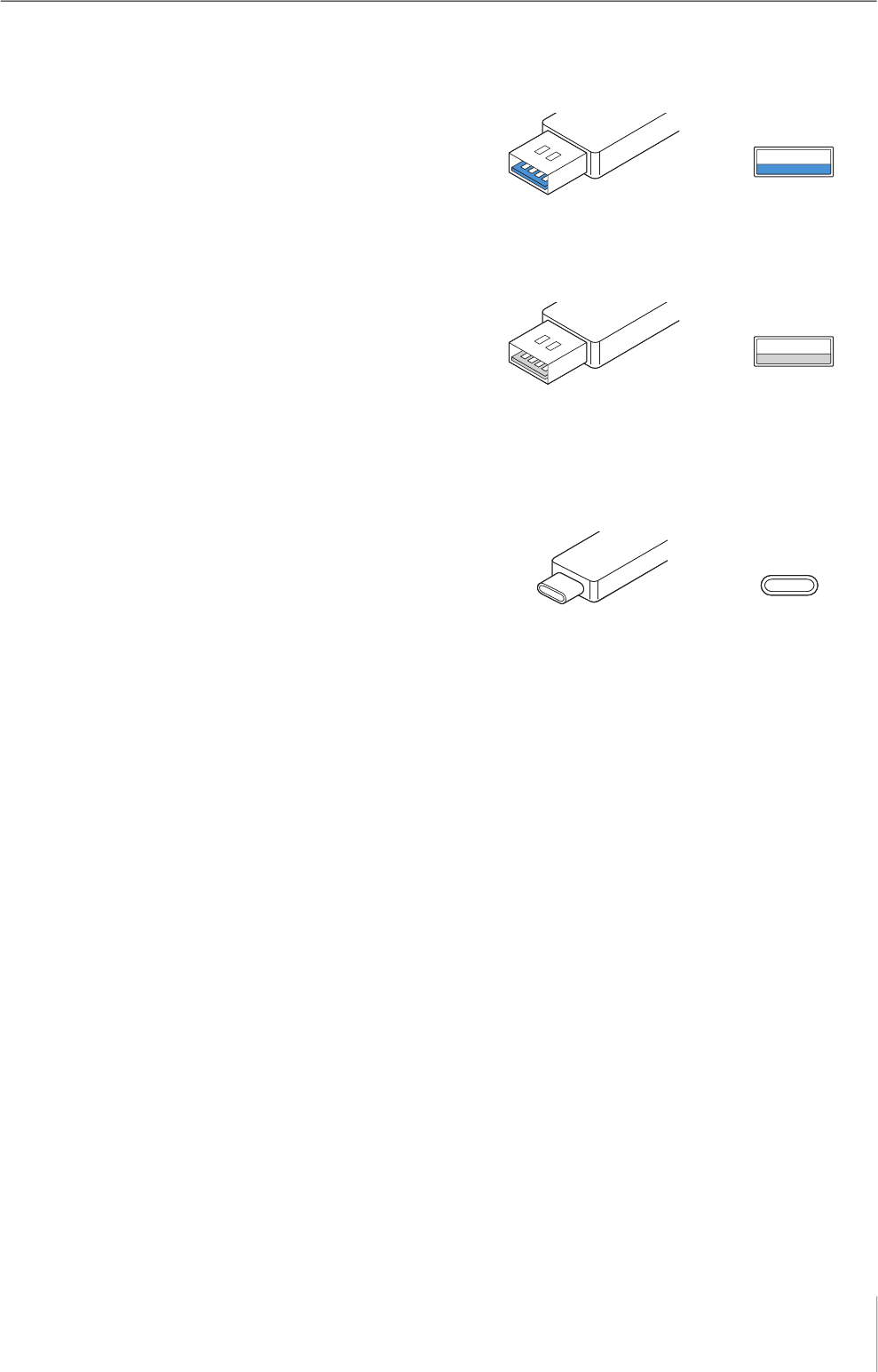
Signal Flows
The following chart indicates the signal flow in the device.
NOTE
• The controllers on the device, such as the [INPUT GAIN] knobs, [OUTPUT] knob are not included in this chart.
• To configure each parameter, use the “dspMixFx UR-C” (page 8) or “Dedicated Windows for Cubase Series” (page 13).
• Please note that you cannot use the built-in Guitar Amp Classics when the sample rate is set to 176.4 kHz or 192 kHz.
*1 The following chart indicates an effect insertion location.
LOOPBACK OFF/ON
From
[MIC/LINE 1]
From
[MIC/LINE 2]
*1
Insert FX
SLOT1
SLOT2
Insert FX
SLOT1
SLOT2
To
[MIDI OUT]
From
[MIDI IN]
To DAW input
From DAW output
USB
To [MAIN OUTPUT]
To [PHONES]
MIX 1
REV-X
REV-X
Send
Level
REV-X
Send
Level
REV-X
Return
Level
FX REC (OFF)
To DAW input
From input on the device
To output on the device
FX REC (ON)
From input on the device
To output on the device
To DAW input
Insert FX
SLOT1
SLOT2
Insert FX
SLOT1
SLOT2
• Set FX REC ON when recording the DSP effect processed signal with the DAW.
• Set FX REC OFF when recording a signal without DSP effect processing with the DAW.
Appendix
UR22C Operation Manual 35
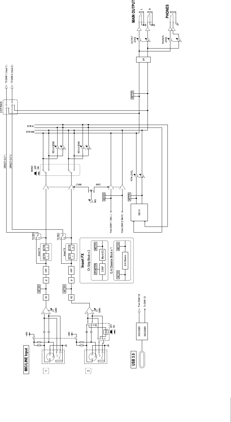
Block Diagrams
44.1kHz, 48kHz, 88.2kHz, 96kHz
Appendix
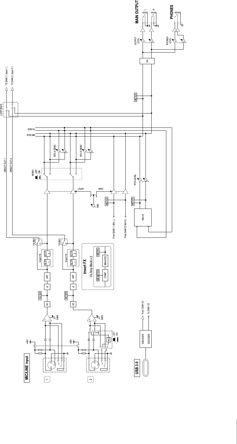
UR22C Operation Manual 36
176.4kHz, 192kHz
Appendix
UR22C Operation Manual 37
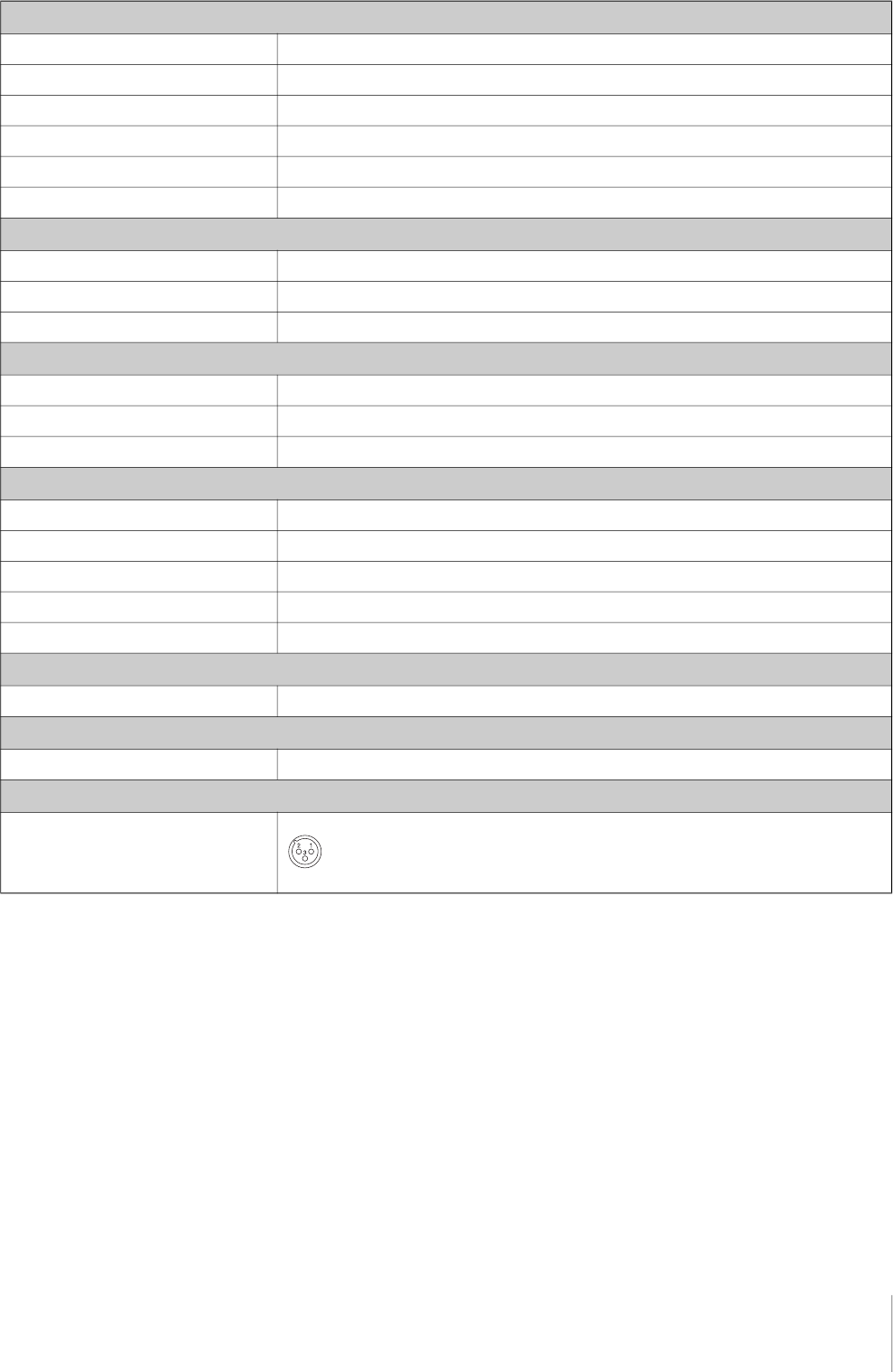
Technical Specifications
MIC INPUT 1/2 (balanced)
Frequency Response +0.0/-0.4 dB, 20 Hz – 22 kHz
Dynamic Range 102 dB, A-Weighted
THD+N 0.003%, 1 kHz, 22 Hz/22 kHz BPF
Maximum Input Level +6 dBu
Input Impedance 4 kΩ
Gain Range +6 dB – +60 dB
HI-Z INPUT 2 (unbalanced)
Maximum Input Level +9.0 dBV
Input Impedance 1 MΩ
Gain Range 0 dB – +54 dB
LINE INPUT 1/2 (balanced)
Maximum Input Level +22 dBu
Input Impedance 18.5 kΩ
Gain Range -10 dB – +44 dB
MAIN OUTPUT (Impedance balanced)
Frequency Response +0.0/-0.2 dB, 20 Hz – 22 kHz
Dynamic Range 105 dB, A-Weighted
THD+N 0.002%, 1 kHz, 22 Hz/22 kHz BPF
Maximum Output Level +12 dBu
Output Impedance 150 Ω
PHONES
Maximum Output Level 15 mW +15 mW, 40 Ω
USB
Specification USB 3.0, 32-bit, 44.1 kHz/48 kHz/88.2 kHz/96 kHz/176.4 kHz/192 kHz
XLR INPUT
Polarity 1: Ground
2: Hot (+)
3: Cold (-)

Appendix
UR22C Operation Manual 38
General Specifications
The contents of this manual apply to the latest specifications as of the publishing date.
To obtain the latest manual, access the Steinberg website then download the manual file.
Power Requirements
4.5 W
Dimensions (W x H x D)
159 x 47 x 159 mm
Net Weight
1.0 kg
Operating Free-air Temperature Range
0 °C – 40 °C
Included Accessories
• USB 3.0 cable (3.1 Gen1, Type-C to Type-A, 1.0 m)
• Startup Guide
• Cubase AI Download Information
• Essential Product Licence Information
• Steinberg Plus Download Information

Uninstalling TOOLS for UR-C
To uninstall the software, you must remove the following
software one by one.
• Yamaha Steinberg USB Driver
• Steinberg UR-C Applications
• Basic FX Suite
Follow the steps below to uninstall TOOLS for UR-C.
Windows
1. Disconnect all USB devices other than the
mouse and keyboard from the computer.
2. Start the computer and log on to the
Administrator account.
Exit any open applications and close all open
windows.
3. Open the window for the uninstall operation
as follows.
[Control Panel] [Uninstall a Program] to call up
the [Uninstall or change a program] panel.
4. Select the software to be uninstalled from
the list.
• Yamaha Steinberg USB Driver
• Steinberg UR-C Applications
• Basic FX Suite
5. Click the [Uninstall] / [Uninstall /Change].
If the [User Account Control] window appears, click
[Continue] or [Yes].
6. Follow the on-screen instructions to remove
the software.
Repeat steps 4 through 6 to uninstall the remaining
software you have not selected.
Uninstalling TOOLS for UR-C is now complete.
Mac
1. Disconnect all USB devices other than the
mouse and keyboard from the computer.
2. Start the computer and log in to the
Administrator account.
Exit any open applications and close all open
windows.
3. Extract the TOOLS for UR-C that you
downloaded in advance.
4. Double-click the following file in the
extracted folder.
• Uninstall Yamaha Steinberg USB Driver
• Uninstall Steinberg UR-C Applications
• Uninstall Basic FX Suite
5. Click [Run] when the “Welcome to the
***uninstaller.” message appears.
The characters *** represent the software name.
After that, follow the onscreen instructions to
uninstall the software.
6. Click [Restart] or [Close] when the
“Uninstallation completed.” message
appears.
7. When the message prompting you to restart
your computer appears, click [Restart].
Repeat steps 4 through 7 to uninstall the remaining
software you have not selected.
Uninstalling TOOLS for UR-C is now complete.
Steinberg Website
https://www.steinberg.net/
Manual Development Group
© 2019 Yamaha Corporation
Published 01/2022 MW-C0
